Pump/piping installation, Installation (continued) – Craftsman 390.262454 User Manual
Page 4
Attention! The text in this document has been recognized automatically. To view the original document, you can use the "Original mode".
INSTALLATION (Continued)
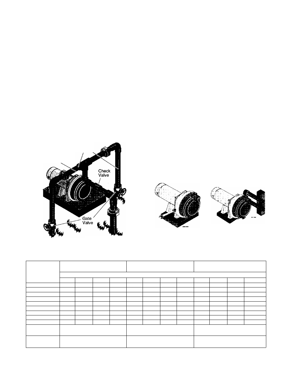
2, To aid priming on driven point installations, install a line
check valve as shown in Figure 2. Be sure check valve
flow arrow points toward pump.
DISCHARGE PIPE SIZES
1. If increasing discharge pipe size, install reducer in pump
discharge tapping. Do not increase pipe size by stages.
2. When the pump is set away from the points of water use,
the discharge pipe size should be increased to reduce
pressure losses caused by friction.
• Up to 100’ run: Same size as pump discharge tapping.
• 100’ to 300’ run: Increase one pipe size.
• 300' to 600’ run: Increase two pipe sizes.
LAW N SPRINKLING APPLICATION
This pump is designed for lawn sprinkling. It is designed to
deliver plenty of water at full sprinkler pressure. It can pump
from a pond, cistern or well points.
Pump discharge can be divided to supply two (2) or more
To
Service
Priming
Plug
846 0494
Figure 3 - Multiple Discharge
sprinkler systems. A suggested multiple discharge to service
is shown in Figure 3-
Do not use in a pressure tank or booster pump
application.
Pump/Piping Installation
PUMP INSTALLATION
NOTICE: Use Teflon tape supplied with the pump for mak
ing all threaded connections to the pump itself. Do not use
pipe joint compounds on the pump: they can react with
the plastic in the pump components.
1. Bolt pump to solid, level foundation.
2. Support all piping cormected to the pump.
3. Wrap 1-1/2 to two layers of Teflon tape clockwise (as you
face end of pipe) on all male threads being attached to
pump.
4. Tighten joints hand tight plus 1-1/2 turns. Do not over
tighten.
NOTICE: Install pump as close to water source as possible.
Long piping runs and many fittings create friction and re
duce flow.
Use schedule 80 or iron pipe. See “Well Pipe InstaUation” for
more information.
Figure 4 - Bolt Pump
Down
Figure 5 - Independently
Support All Piping
Attached To Pump
TABLE II - PERFORMANCE CHART (IN GALLONS PER MINUTE)
DISCHARGE
PRESSURE
PSI
390.262454
1 H.P.
390.262553
1-1/2 H.P.
390.262653
2 H.P.
DISTANCE ABOVE TO WATER
5’
10’
15’
20’
5’
10’
15’
20’
5’
10’
15’
20’
10
55
49
48
45
67
61
56
46
69
67
65
62
15
51
46
45
44
66
58
55
45
65
63
60
58
20
45
42
39
37
61
56
54
44
59
56
54
52
25
38
35
32
29
55
52
51
43
52
50
48
45
30
31
28
24
20
48
45
44
37
47
45
42
40
35
23
19
16
11
39
37
34
28
42
38
35
32
40
17
13
8
-
33
27
20
11
34
30
27
23
45
-
-
-
18
14
8
-
25
18
13
10
50
_
-
-
_
-
-
14
7
-
-
DISCHARGE
PIPE TAPPING
1-1/2” NPT
1-1«” NPT
2” NPT
SUCTION
PIPE TAPPING
1-1/2” NPT
1-1/2” NPT
2” NPT