Removing unit from carton, Loose parts, Tools required – Craftsman 247.388240 User Manual
Page 7: Disconnecting spark piug, Assembiing handle, Assembly
Attention! The text in this document has been recognized automatically. To view the original document, you can use the "Original mode".
ASSEMBLY
Removing Unit From Carton
•
Remove staples, break glue on top flaps, or cut
tape at carton end and peel along top flap to
open carton.
‘
•
Remove loose parts if included with unit (i.e.,
owner’s manual, etc.).
•
Cut along dotted lines and lay carton down flat.
•
Remove packing material. Roll unit out of
carton. Check carton thoroughly for loose parts.
Note:
Make sure not to crimp the cable while
removing loose parts or the unit from the carton.
IMPORTANT:
This unit is shipped
without gasoline
or oil in the engine.
Be certain to service engine with
gasoline and oil before operating your mower.
NOTE:
Reference to right or teft hand side of the
mower and/or front or behind the mower is observed
from the operating position.
Loose Parts
a. Owner’s Manual
b. A Bottle of Engine Oil
c. Parts for Grass Bag: Frame, Bag
d. Discharge Chute
Tools Required
a. Pair of Pliers
b. Funnel
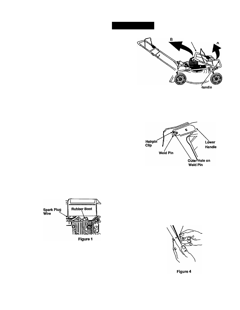
Disconnecting Spark Piug
•
Before setting up your lawn mower, disconnect
the spark piug wire from the spark plug, and
ground it against the engine. See Figure 1.
•
Attach rubber boot to a bolt on the engine to
ground as shown below.
'Spark Plug
Assembiing Handle
• Raise lower handle in direction A shown in
Figure 2. It should snap into place.
Note:
Make sure to route the cable inside the iower
handle. Also do not crimp the cable while lifting the
handle up
Upper Handle
Lowerl
Figure 2
For shipping purposes, the hairpin clip is placed in the
outer hole of the weld pin on the lower handle.
• Remove the hairpin clip from the outer hole of
the weld pin. See Figure 3.
Figure 3
Using a pair of pliers, insert the hairpin clip into
the inner hole in the weld pin. See Figure 3.
Repeat on other side.
Raise the upper handle in the direction B shown
in Figure 2. Tighten the wing nuts which are
already on the handle.
Attach control cable to the lower handle with the
cable tie already on the lower handle. Pull tight
the cable tie and cut off extra. See Figure 4.
Cable Tie