Specifications, Software driver, Conformance – CH Tech EM405D100 User Manual
Page 2: Ordering information
Rev. *
Specifications:
Implementation:
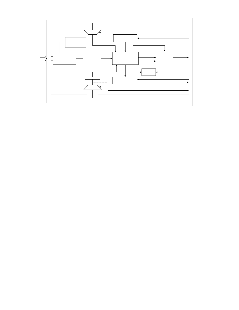
• All versions use either two (2), four (4) or eight (8)
ANSI/VITA Standard 16 Channel M-Modules
(MA203), each of which have the block diagram
shown above
• See the EM405D and EM405-8 on C&H web site for
further information on the instrument enclosure
mounting and dimensions.
Trigger/Sample Strobe Features:
• An external clock may be routed through one
mezzanine to a carrier trigger and back to the Event
Detector triggers to minimize skew between
channels
• One mezzanine’s clock may be used as a master in
a similar manner
External Trigger Inputs:
• 32 Channel Unit
TTL
• 64 & 128 Channel Units
TTL and LVDS
External Power (32 Channel Unit):
• AC Input 100 to 240VAC, 47 to 63Hz with furnished
adapter
• Alternatively DC powered by 12V, 1A
External Power (64 and 128 Channel Units):
• AC Input 85 to 265VAC, 47 to 63Hz
• Alternatively DC Powered by 36 to 75V
Software Driver:
• Windows DLL
• Soft Front Panel Executable
• Online Help
• LabWindows/CVI Function Panels
• ANSI-C Source Code
• LabView
Conformance:
• These modules will be CE compliant for Emissions,
Immunity and Safety
Ordering Information:
32 Channel Event Detector:
Model EM405D100
P/N 11030010-0001
64 Channel Event Detector:
Model EM405-8x10⁶
P/N 11030010-0002
128 Channel Event Detector:
Model EM405-8x10⁷
P/N 11030010-0003
DEBOUNCE
M-MODULE
I/F
TIMER
31-BIT
SAMPLE
AND
STORE
LOGIC
FIFO
RESET
PROGRAM
TRIGGER A OR B
EXTCLK
MEMORY
48-BIT
CONTROL
STORE
FRONT
PANEL I/O
WATCH
MASK
CLOCK
10KHz
- 5MHz
INTERRUPT
LOGIC
PROGRAM
CONTROL
RUN
SCLK
TRIGGER A OR B
SW
EXTRUN
SIGNAL
CONDITIONING
ACCESSORY
MODULE
ISOLATED
DC-DC
CONVERTER
INTERRUPT
PRESCALER
TRIGGER A OR B
INPUT
SIGNALS