Front wheel tqe-in/camser – Craftsman 917.256544 User Manual
Page 23
Attention! The text in this document has been recognized automatically. To view the original document, you can use the "Original mode".
5;4r|b..-~iL: Uiii-UJ-i HHR-bb iUib
-js,^ ’ M«bn! iTvio '’Vj... :,“i .diîj
■ il M. '! I,
h
' h^uS. It eii'Mf.'r-ii."Nc I ' J ’ ^ f ’ f i ' r ' f ^
iH‘i ; r <-i;t"-’:f h ii li ¡',.") 5--,}i".Mii
T!,;c-J|tf’ .' ■:
i’■he 1
i ..-
îî
i se ■> c-J-''
\ u ■ f *
• Î jIh'A V
t
r., i!-.: -
t'. r. ■ r. I‘* '( .'III-.I l'’^)
'
I. . • r 1
. i w f ri' -i" K' hf- 'j '
• “ii! , C'-iiib> [iKl !if>T! >jfMi.Ji!t k~',vi !" 1 i' !* ''V ' fr
h . !. r*'“ ‘i f' n S' I Î- 'nc ih
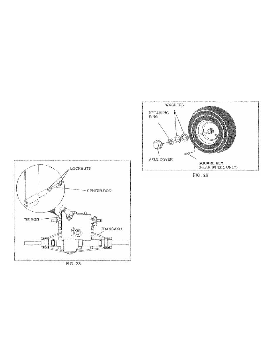
» righ-ren !oci es'Mêr- eifT ? £' i'Ep . ¡jr^uTeij. u,ics, ra,s FIG. 27 TO ADJUST STEERING WHEEL ALIGNMENT !f steering wheel crossbars are not horizontal (left to right) when wheels are positioned straightforward, remove steer ing wheel and reassemble per instructions in the Assembly scîction of this rnarsual. FRONT WHEEL TQE-IN/CAMSER Thfi front wheel toe-in and camber are not adjustable on wheel toe-in or camber, contact your nearest authorized service centsr/deparimenî. b }' UrNO¥F. TAILLJ Ft.'F ■ boj ,.d: G ' I j[ .1 'ii, b m..'- 'Sf,iclufiiingnnc ¡111 / bed r*-isv.t3( UÉ.” f • -o.rjii s s eg > r* b-i or |- t '-po'r fur ■.eo'st.mtG ,n r'r,r Viherî- niy ugncroovhc n rear'A'hei.i f:Lb . r-o n ' k iti^' n -^quoi-' fiO' ■ P ".vrlv-îS ~.n'i ‘VC-if fct uriiig iPCj oewj-« I-’ i'! axle groove. ® Ffepiace axle cover. TO. START ENGINE WITH A WEAL E-fATTERY (See Fig. 30) A CAISTIOI'I: Leiad-srrid fcatterse-*? gener™ 0 rle.s. If your baltery rs too wo.ak trs start the engine, it should be recharyod. If "jumper cebims' are usofi for emergency siailMig. follow Ihio procedure-' IMFOPTAHT 7GUP TRACTOR iS EUiilPPftP WITH A 12 VOLT NEGATIVE GROUNDER S'f-STEM. THE OTHER VEiHiCLE MUST ALSO Bff A 12 VOLT NFGATIVE OnOUNDEO S y 'STEM DO HOT USE YOUR TRACTOR PATTL-R'Y to . start DTHEFi VEHICLES, TO ATTACH JUMPER, CABLES - • Connect each end of the RED cable to the POSITIVE ' ® Connect one end of the BLACK cable to the NE-IGA~ TIVE (-} terminal of fully charged battery. • Connect the other end of the E-LACK cable to good TO REMOVE CABLE-3, REVELRSE ORDER - charged battery. • RED cable test from both batteries. 23
your treictor, !f damage has occurred to affect the front
ote erxplosive gases. Keepsparhs, flame
arjcf srsiokin.g №31611.31.3 away from bat
teries. Aiwaifs iMear eye pretecliori
wEsen around bati
(+) terminal of each battery, taking care not to short
against chassis,
CHASSIS GROUND, awayfromfueltankand battery.
® BLACK cable first from chassis and then irom the fully