Operation – Craftsman 315.284620 User Manual
Page 27
Attention! The text in this document has been recognized automatically. To view the original document, you can use the "Original mode".
OPERATION
WARNING: To reduce the risk of injury, aiways
make sure the rip fence is paraiiei to the biade before
beginning any operation.
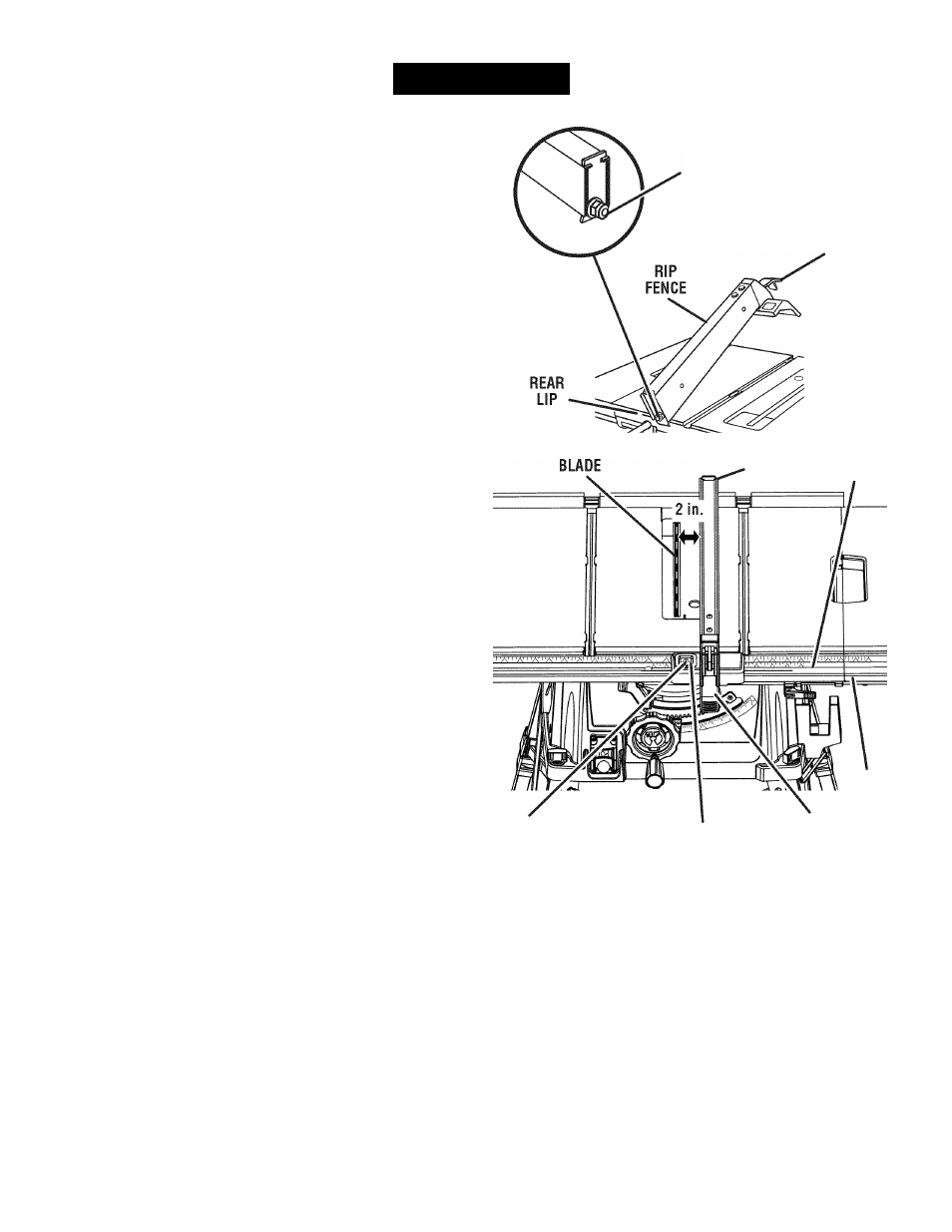
TO USE THE RIP FENCE
See Figure 31.
■ Piace the rear iip on the rear of the saw tabie and puii
siightiy toward the front of the unit,
■ Lower the front end of the rip fence onto the guide
surfaces on top of the front raii.
■ With the rip fence fiat on the saw table, push the fence
towards the front rail to align the fence to the saw
table.
■ Push the locking lever down to align and secure the
fence.
Check for a smooth gliding action. If adjustments are
needed, see To Check the Alignment of the Rip Fence
to the Blade in the Adjustment section of this manual.
■ Make two or three test cuts on scrap wood. If the cuts
are not true, repeat the process.
NOTE: The rip fence must be secure when the locking
handle is engaged. To increase the grip of the rip fence
on the rear lip of the table, tighten the clamp screw on
the rear of the rip fence by turning it clockwise.
TO SET THE RIP FENCE SCALE INDICATOR TO
THE BLADE
See Figure 31.
Use the indicator on the rip fence to position the fence
along the scale on the front rail.
NOTE: The anti-kickback pawls and blade guard assem
bly must be removed to perform this adjustment. Reinstall
the blade guard assembly when the adjustment is com
plete.
Begin with the blade at a zero angle (straight up).
■ Unplug the saw.
■ Loosen the rip fence by lifting the locking lever,
■ Using a framing square, set the rip fence 2 in, from the
blade tip edge.
■ Loosen the screw on the scale indicator and align with
the 2 in, mark as shown,
■ Tighten the screw and check the dimension and the rip
fence.
CLAMP
SCREW
LOCKING
LEVER
RIP
C f f t i c
FENCE
FRONT
RAIL
2 in.
MARK
SCALE
INDICATOR
LOCKING
LEVER
Fig. 31
27