Assembly – Craftsman 358.795800 User Manual
Page 5
Attention! The text in this document has been recognized automatically. To view the original document, you can use the "Original mode".
responsible for maintaining the operat
ing condition of these parts. Failure to
do so is a violation of the law. For nor
mal homeowner use, the muffler and
spark arresting screen will not require
any service. After 50 hours of use, we
recommend that your muffler be ser
viced or replaced by your Sears Service
Center.
ASSEMBLY
CARTON CONTENTS
Check carton contents against the fol
lowing list.
Model 358.795800
• Brushcutter
• Cupped washer
• Large nut for installing blades
• Hex wrench
• Handlebar
• Bracket cover
• Bracket cover screws (2)
• Metal blade shield
• Blade shield screws (4)
• 4-Point weed blade
• 8-Point weed blade
• Plastic shield
• Wing nut (screwed onto shield)
• Trimmer head (assembled on unit)
• Shoulder strap with warning
• Container of line
• Container of oil
Examine parts for damage. Do not
use damaged parts.
NOTE:
If you need assistance or find
parts missing or damaged, call
1-800-235-5878.
It is normal for the fuel filter to rattle in
the empty fuel tank.
Finding fuel or oil residue on muffler is
normal due to carburetor adjustments
and testing done by the manufacturer.
ASSEMBLY
^WARNING:
Always stop unit
and disconnect spark plug before per
forming any assembly procedures.
^ WARNING:
if received as
sembled, repeat all steps to ensure
your unit is properly assembled and all
fasteners are secure.
TOOLS REQUIRED
• Hex Wrench (provided)
• Adjustable Wrench
• Phillips Screwdriver
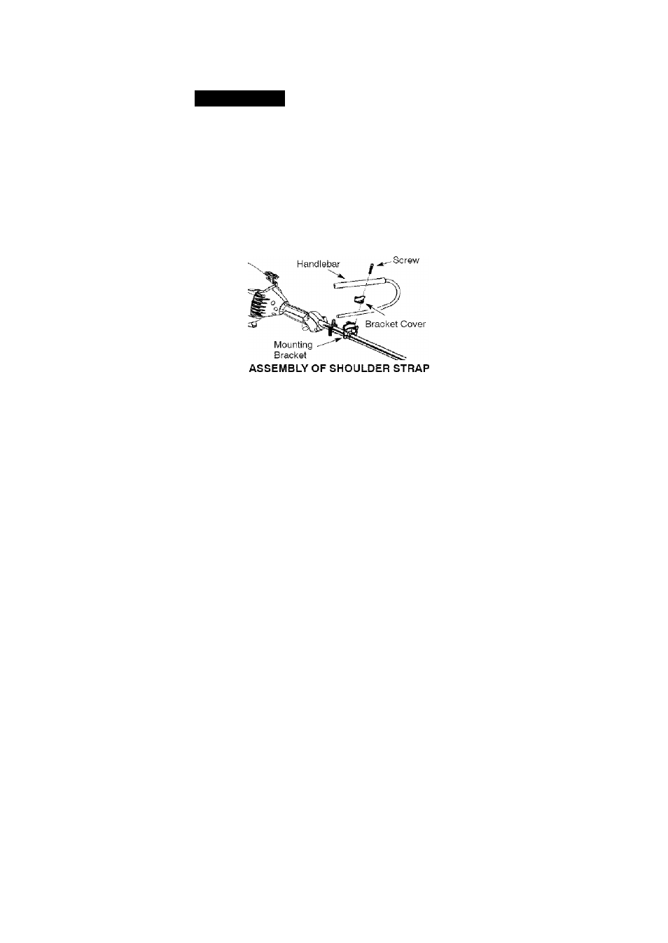
ATTACHING THE HANDLEBAR
A
DANGER:
To avoid serious inju
ry, the barrier portion of the handlebar
must be installed as shown to provide a
barrier between operator and the spin
ning blade.
1. Locate the decal on the handlebar.
This decal includes an arrow. Posi
tion the handlebar with the mount
ing bracket at the end of the arrow.
2. Position the bracket cover over the
handlebar. Again make sure the
handlebar is at the end of the arrow.
3. insert screws and hand tighten
only. Be sure the handlebar is
installed correctly; then, tighten
each screw securely with the hex
wrench.
liWARNING:
Proper shoulder
strap and handlebar adjustments must
be made with the engine completely
stopped before using unit.
1. Insert your right arm and head
through the shoulder strap and al
low it to rest on your left shoulder.
Make sure the danger sign is on
your back and the hook is to the
right side of your waist.
NOTE: A one-half twist is built in the
shoulder strap to allow the strap to rest
flat on the shoulder.
2. Adjust the strap, allowing the hook
to be about 6 inches below the
waist.
3. Fasten the strap hook to the clamp
located between the trigger handle
and the handlebar clamp base and
lift the tool to the operating position.
4. Try on shoulder strap and adjust
for fit and balance before starting
the engine or beginning a cutting
operation.
NOTE: It may be necessary to relo
cate the shoulder strap clamp on the
shaft for proper balancing of unit.