Craftsman 137.248840 User Manual
Page 11
Attention! The text in this document has been recognized automatically. To view the original document, you can use the "Original mode".
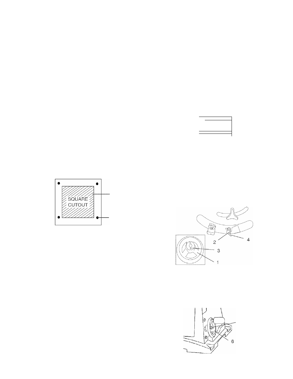
MOUNT SAW ON WORK SURFACE (FIG. C)
1. If the leg set will not be used, the saw must be
properly secured to a sturdy workbench using the
four mounting holes at the base of the saw.
2. The surface of the table where the saw is to be
mounted must have a hole large enough to facilitate
sawdust fall-through and removal.
3. Square the saw on the mounting surface and mark
the location of the four 3/8 in. mounting holes (1).
4. Drill 3/8 in. hole into the mounting surface.
5. Mark an 11 in. square (2) centered between the four
mounting holes (1).
6. Cut out and remove the square.
7. This opening will allow sawdust to fall through the
saw base.
8. Place the saw on the work surface, and align the
mounting holes of the saw with those drilled through
the surface.
9. Fasten the saw to the work surface.
INSTALLING THE DUST BAG (FIG. D)
A WARNING
Do not operate this machine on the floor. This is
very dangerous and may cause serious injury.
Fig. C
A
WARNING
Failure to provide the sawdust fall-through hole for
use of the saw when mounted to a work surface and
not the stand will cause sawdust to build up in the
motor area, which may result in fire or cause motor
damage.
A
WARNING
Always keep your work area clean, uncluttered and
well lit.
A WARNING
Do not use this saw to cut and/or sand metals. The
hot chips or sparks may ignite sawdust or the bag
material.
Place the dust bag around the neck of the dust
chute and tie the dust bag pulling the string tight
and secure with the spring-loaded tie clip.
Fig. D
P.
^ imN rj i
.
‘ I
I V
■ W 7 '
!
i
I
i
0
V, \/ ^
L
BLADE RAISING HANDWHEEL (FIG. E, F)
1. Attach the up - down handwheel (1) to the elevation
rod (2) at the front of the saw. Make sure the slots (3)
in the hub of the handwheel {1) engage with the
pins (4).
2. Attach and tighten the dome nut (5 - Fig. F).
Fig. E
BLADE TILTING HANDWHEEL (FIG. F)
1. Attach the bevel 0° ~ 45° handwheel (6) to the blade
tilting rod on the right side of the saw in the same
manner as above.
2. Attach and tighten the handwheel dome nut (5).
Fig. F
11