Craftsman 486.248400 User Manual
Page 8
Attention! The text in this document has been recognized automatically. To view the original document, you can use the "Original mode".
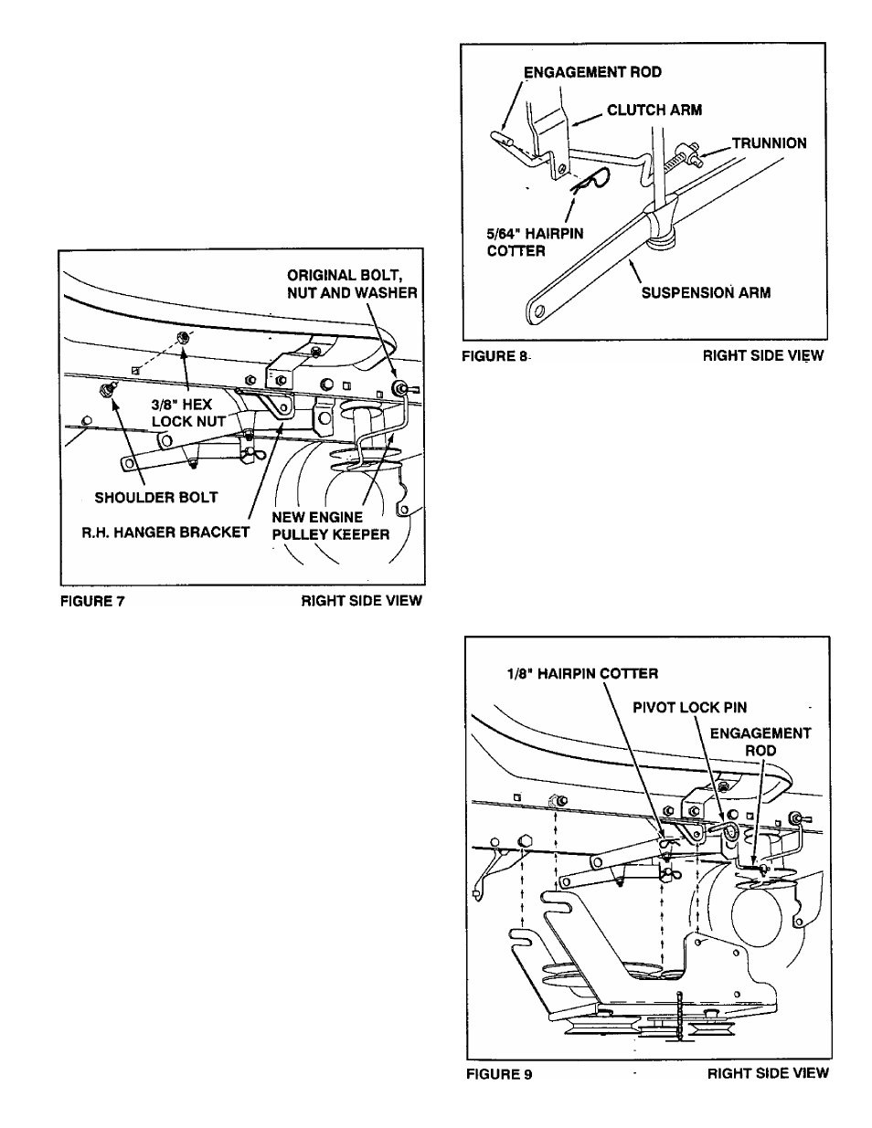
• Assemble a shoulder bolt arid 3/8" hex lock nut to
the R.H. side of the tractor frame, using the first
empty hole to the rear of the R.H. hanger bracket.
See figure 7
• Replace the engine puiley keeper on your tractor
with the new pulley keeper supplied with the snow
blower. Attach the keeper to the frame using the
originai bolt, washer and nut. See figure 7.
NOTE: Some tractors may already be equipped
with an identical pulley keeper.
INSTALLING THE CLUTCH/IDLER ASSEMBLY ON
TRACTORS WITH MANUAL ATTACHMENT
CLUTCHES (Use these instructions if your tractor
has an attachment clutch lever on the dash panel
for starting and stopping the mower deck.)
• Move the attachment clutch lever on the dash
panel to the disengaged (down) position.
• Screw the trunnion onto the end of the engagement
- rod as shown in figure 8.
• Locate the clutch arm which is found underneath
the right hand side the tractor, just to the inside of
the suspension arm. This is the arm that the mower
clutch rod was connected to. This arm wili move
fo™rard and backward if the attachment clutch lever
on the dash panel is moved.
• Position the engagement rod to the inside of the
clutch arm and insert the drilled end of the rod
through the arm. Secure with a 5/64" hairpin cotter.
Seeiigure 8.
; "
• Be sure that the loose end of the engagement rod
is lifted up toward the front of the tractor (as shown
in figure 9) when performing the next operation.
You can temporarily support the rod using a rubber
band tied to the engine pulley keeper.
• Attach the snow thrower's clutch/idler assembly to
the tractor frame by sliding the notched arms at the
rear of the assembly onto the two shoulder bolts
assembled to the Inside of the tractor frame. Lift
the front of the assembly, fitting the sides into the
R.H. and L.H. hanger brackets. Attach the assem
bly to the brackets using two pivot lock pins and
1/8" hairpin cotters. See figure 9.