Assembly, To remove generator from carton, Installing wheel kit – Craftsman 580.327071 User Manual
Page 6: Grounding the generator
Attention! The text in this document has been recognized automatically. To view the original document, you can use the "Original mode".
ASSEMBLY
Your AC generator was completely assembled at the fac
tory It is ready for use after it has been properly serviced
with the recommended lubricating oil and fuel
IF YOU HAVE ANY PROBLEMS WITH THE ASSEMBLY
OF YOUR GENERATOR, PLEASE CALL THE GENER
ATOR HELPLINE AT 1*800-222-3136.
IMPORTANT: ANY ATTEMPT TO RUN THE ENGINE
BEFORE IT HAS BEEN SERVICED WITH THE RECOM
MENDED OIL WILL RESULT IN AN ENGINE FAILURE.
TO REMOVE GENERATOR FROM CARTON
» Set the carton on a fiat rigid surface with “THIS SIDE
UP” arrows pointing upward.
•
Carefully open the top flaps of shipping carton
» Gut down corners at one end of shipping carton and lay
that side of carton down flat.
•
Remove packing material, carton fillers, etc
«. Remove generator from shipping carton
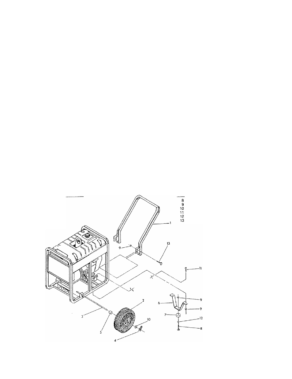
INSTALLING WHEEL KIT
The Sears Wheel kit was designed to greatly improve the
portability of the 8000 watt Sears Craftsman Deluxe Gen
erator install the Wheel Kit as follows;
o Place the generator on a flat hard surface,
e Slide axle (Item 3) through holes in the brackets pro
vided on the generator cradle (Fig 1) and then add the
S) spacers {¡letn 5) on each protruding end of the axie
e Stand at engine end of generator and gently tilt gener
ator forward high enough to prop up front of the cradle,
This will allow you to add the wheels,
*
Slide on the wheels (Item 2} on each end of the axle
and retain each with 5/8” washer (Item 10) and retain
ing pin (Item 4), Lower the generator.
» Attach the vibration mount (Hem 7) to the support leg
(Hem 6) with M8 X 30mm capscrew (Item 8), MB washer
(Item 12) and M8 lock nut (Item 9} using the combina
tion wrench.
• With the wheels on, you can now tilt the generator end
forward and attach the support leg with two M8 x 20mm
capscrews (Item 11 ) and two lock nuts.
o Set the qenerator down so it is level and, using the
combinalon wrench, attach the handle with four M8 x
45mm capscrews and four lock nuis
GROUNDING THE GENERATOR
The National Electrical Code requires that the frame and
external electrically conductive parts of this generator be
properly connected to an approved earth ground. Local
electrical codes may also require proper grounding of the
unit. For that purpose, a GROUNDING WING SCREW is
provided on the base of the cradle (Fig. 2 on Page 5).
Generally, connecting a No 12 AWG (American Wire
Gauge) stranded copper wire to the grounding screw and
to an earth-driven copper or brass grounding rod (elec
trode) provides adequate protection against electrical
ITEM DESCRIPTION
ITEM DESCRIPTION
HANDLE
WHEEL
AXLE
RETAINING PIN
WHEEL SPACER
SUPPORT LEG
VIBRATION MOUNT
HEX HEAD CAPSCREW. MB x 30mm
LOCK NUT, MS
FLAT WASHER (WHEEL)
HEX HEAD CAPSCHEW, MS X 20mm
FLAT WASHER (VIBRATION MOUNT)
HEX HEAD CAPSCREW. MB x 45mm
FIG. I