Craftsman 917.273638 User Manual
Page 23
Attention! The text in this document has been recognized automatically. To view the original document, you can use the "Original mode".
TO REPLACE MOTION DRIVE BELT
Park the tractor on level surface. Engage
parking brake. For assistance, there is a
belt installation guide decal on bottom side
of left footrest.
BELT REMOVAL -
1. Remove mower (See “TO REMOVE
MOWER” in this section of manual).
NOTE: Observe entire motion drive belt
and position of all belt guides and keepers.
2. Disconnect clutch wire harness.
3. Remove clutch locator.
4. Remove belt from stationary idler and
clutching idler.
5. Remove belt downward from engine
pulley and around electric clutch.
6. Pull belt slack toward rear of tractor.
Remove belt upwards from transaxle
pulley by deflecting belt keepers.
7. Remove belt from center span keeper
and pull belt away from tractor.
BELT INSTALLATION -
1.
2
.
3.
4.
5.
6
.
7.
8
.
Carefully work new belt down between
transaxle belt keepers and onto the
input pulley.
Slide belt into the center span keeper.
Pull belt toward front of tractor and roil
belt around electric clutch and onto
engine pulley.
Install belt through stationary idler and
clutching idler.
Reinstall clutch locator and tighten nut
securely.
Reconnect clutch harness.
Make sure belt is in all pulley grooves
and inside all belt guides and keepers.
Install mower (See “TO INSTALL
MOWER” in this section of manual).
Electric
Clutch
Clutching
Idler
Stationary
Idler
Clutch
Locator
Clutch
Wire
Harness
Center Span
Keeper
Transaxle
Pulley
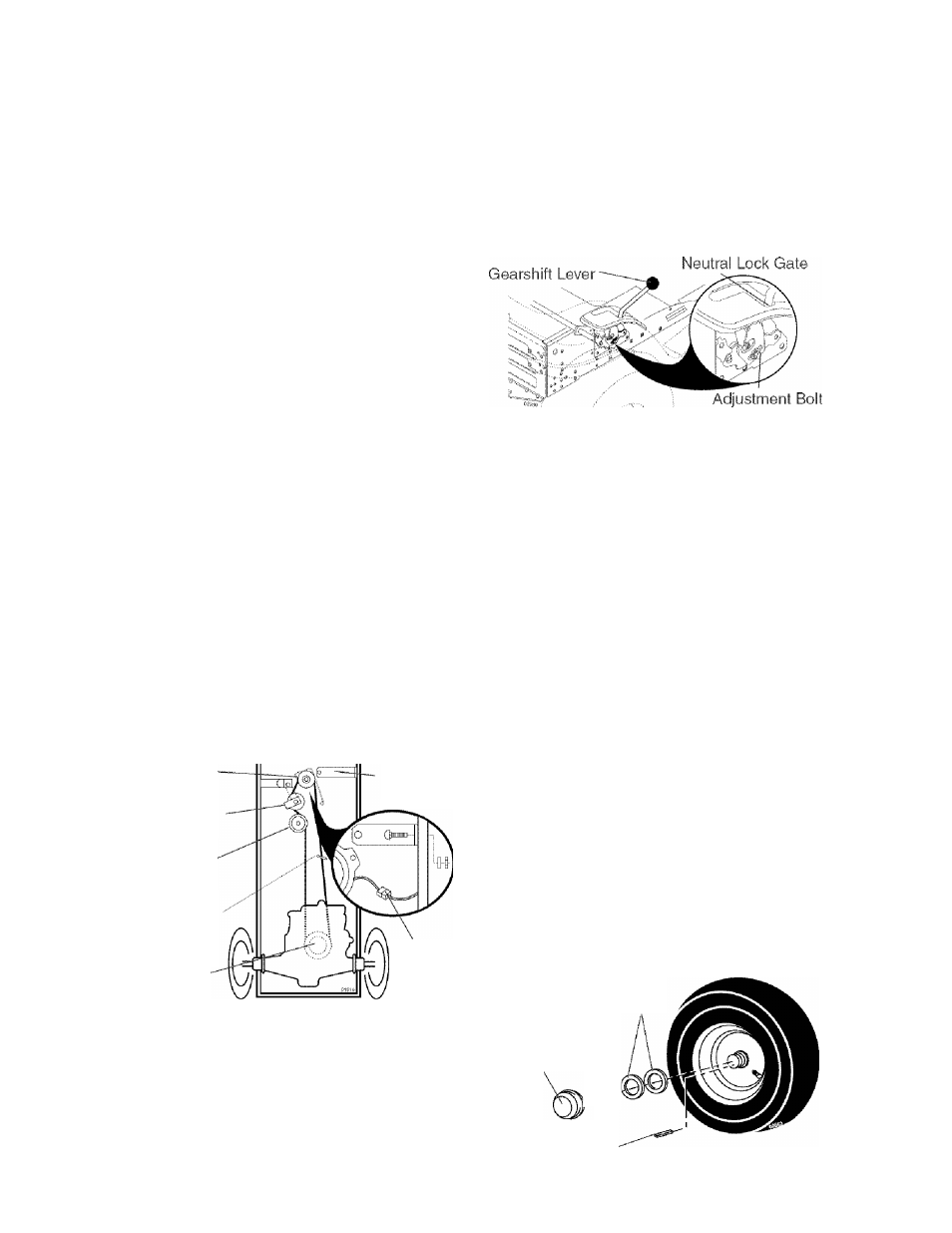
TRANSAXLE GEAR SHIFT LEVER NEU
TRAL ADJUSTMENT
The transaxle should be in neutral when
the gear shift lever is in neutral (N) (lock
gate) position. The adjustment is preset
at the factory; however, if adjustment is
needed, proceed as follows:
1. Make sure transaxle is in neutral (N).
NOTE: When the tractor rear wheels move
freely, the transaxle is in neutral.
2. Loosen adjustment bolt in front of the
right rear wheel.
3. Position the gear shift lever in the neu
tral (N) position.
4. Tighten adjustment bolt securely.
NOTE: If additional clearance is needed
to get to adjustment bolt, move mower
deck height to the lowest position.
TO ADJUST STEERING WHEEL ALIGN
MENT
If steering wheel crossbars are not
horizontal (left to right) when wheels are
positioned straight forward, remove steer
ing wheel and reassemble with crossbars
horizontal,Tighten securely.
FRONT WHEEL TOE-IN/CAMBER
The front wheel toe-in and camber are not
adjustable on your tractor. If damage has
occurred to affect the front wheel toe-in or
camber, contact a Sears or other qualified
service center.
TO REMOVE WHEEL FOR REPAIRS
1. Block up axle securely.
2. Remove axle cover, retaining ring and
washers to allow wheel removal (rear
wheels have a square key - Do not
lose).
3. Repair tire and reassemble.
NOTE: On rear wheels only: align
grooves in rear wheel hub and axle, insert
square key.
4. Replace washers and snap retaining
ring securely in axle groove.
5. Replace axle cover,
NOTE: To seal tire punctures and prevent
flat tires due to slow leaks, purchase and
use tire sealant from Sears. Tire sealant
also prevents tire dry rot and corrosion.
Washers
Retaining
Axle R'"9\
Cover
r
Square Key
(Rear Wheel Only)
23