Pin assignment, Digital rgb connector (9-pin), Vtr connector (8-pin) – Sony PVM-1341 User Manual
Page 14: Specifications
Attention! The text in this document has been recognized automatically. To view the original document, you can use the "Original mode".
Specifications
Pin assignment
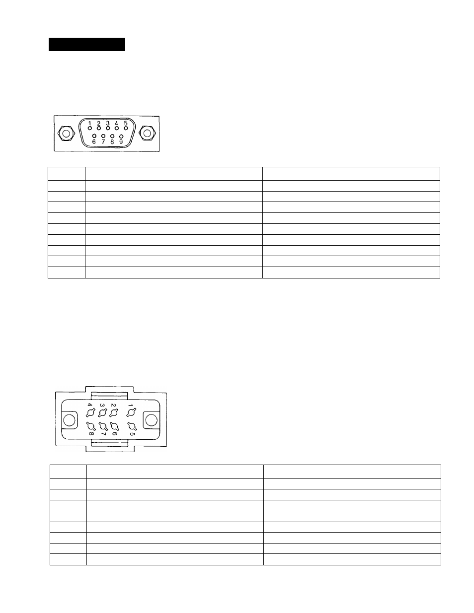
DiGiTAL RGB connector (9-pin)
Pin No.
Signal
Signal level
1
GND (ground)
Ground
2
GND for the signal
Ground
3
Red input
Positive polarity (TTL level)
4
Green input
t
5
Blue input
t
6
Intensity
t
7
NC (no connection)
8
H-SYNC
Positive or negative polarity (TTL level)
9
V-SYNC
Same polarity as H-SYNC (TTL level)
If the intensity function of Pin No. 6 is not used, set the
internal switch on the Qd board to the B position, and
connect the Pin No. 6 to the GND. With this setting, when the
positive intensity signal synchronized to the characters on
the screen is fed, the luminance of the characters will be
increased.
It the specific intensity function, such as that of an IBM
microcomputer, is used, set the internal switch on the Qd
board to the A position, and feed the intensity control signal
to Pin No. 6.
VTR connector (8-pin)
Pin No.
Signal
Description
1
Audio input
-5 dBs, high input impedance (more than 47 kilohms)
2
Video input
Composite 1 Vp-p, sync negative, 75 ohms
3
GND
GND
4
NC
—
5
GND
GND
6
GND
GND
7
GND
GND
8
GND
GND
14