Chateau – Vermont Casting ChateauTM DVT38IN User Manual
Page 17
17
Chateau™
20011956
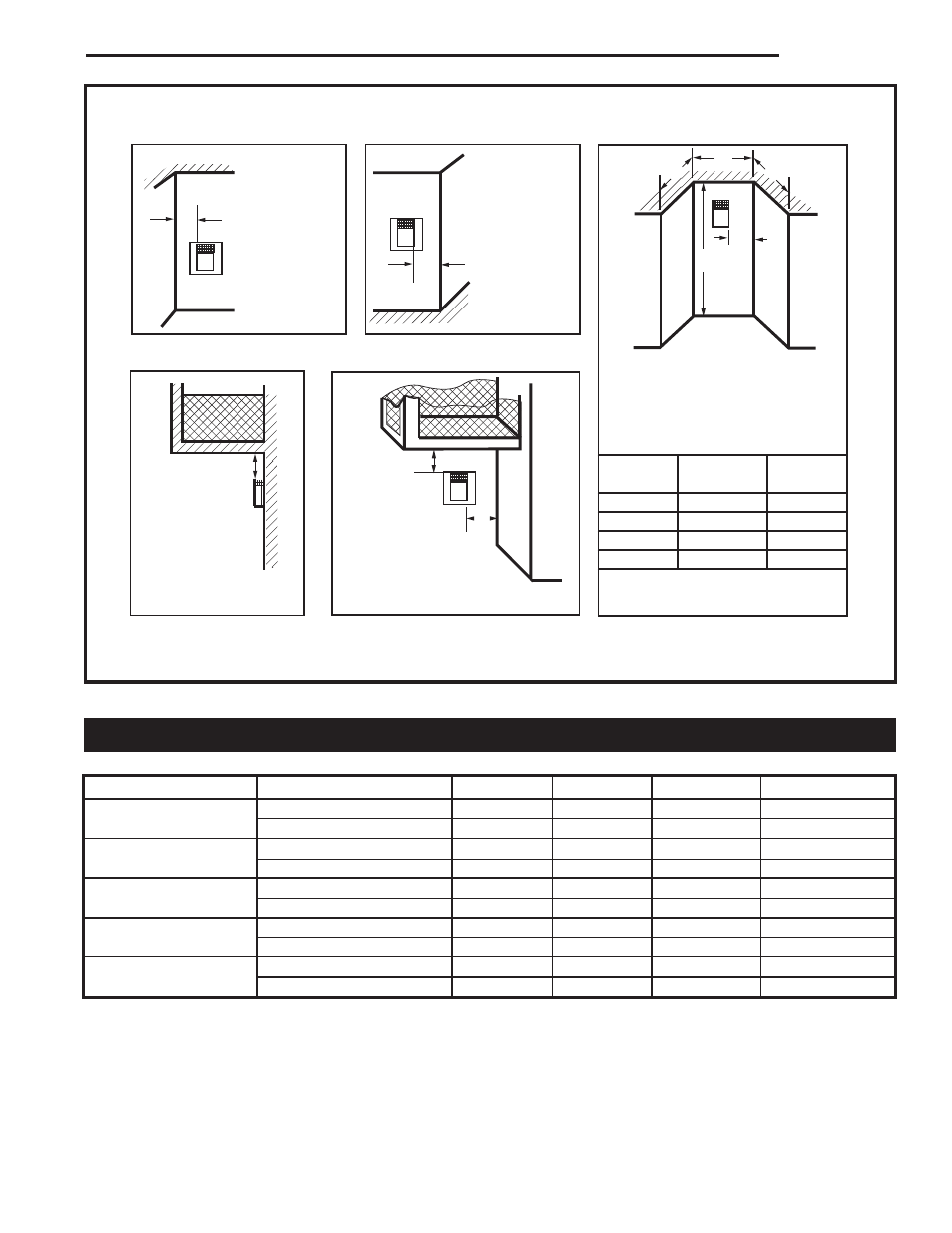
Fig. 14 Termination clearances.
Quick Reference for Fresh Air Restrictor Plate / Flue Baffle
Application
Item
DVT38N
DVT38P
DVT44N
DVT44P
SK8DVSK
Flue Restrictor Plate
3”
None
None
4¹⁄₂”
Fresh Air Restrictor Plate
None
None
None
#1
Vertical Less than 12’ Flue Restrictor Plate
None
None
None
None
Fresh Air Restrictor Plate
None
None
None
None
Vertical 12’ to 20’
Flue Restrictor Plate
4¹⁄₂”
4¹⁄₂”
4¹⁄₂”
4¹⁄₂”
Fresh Air Restrictor Plate
#3
#3
#3
#3
Vertical 20’ to 30’
Flue Restrictor Plate
4¹⁄₂”
4¹⁄₂”
4¹⁄₂”
4¹⁄₂”
Fresh Air Restrictor Plate
#2
#2
#2
#2
Vertical 30’ to 40’
Flue Restrictor Plate
4¹⁄₂”
4¹⁄₂”
4¹⁄₂” or 6³⁄₄”
4¹⁄₂” or 6³⁄₄”
Fresh Air Restrictor Plate
#1
#1
#1
#1
Outside Corner
Inside Corner
Termination Clearances
Termination clearances for buildings with combustible and noncombustible exteriors.
G =
Combustible
6" (152 mm)
Noncombustible
2" (51 mm)
F =
Combustible
6" (152 mm)
Noncombustible
2" (51 mm)
G
Balcony -
with no side wall
M =
Combustible &
Noncombustible
12" (305 mm)
M
Balcony -
with perpendicular side wall
M = 24" (610 mm)
P = 20” (508 mm)
M
F
Alcove Applications*
C
D
C
E
V
V
Combustible &
Noncombustible
V
V
V
E
= Min. 6” (152 mm) for
non-vinyl sidewalls
Min. 12” (305 mm) for
vinyl sidewalls
O
= 8’ (2.4 m) Min.
O
P
584-15
No.
of Caps
D
Min.
C
Max.
1
3’ (914 mm) 2 x D
Actual
2
6’ (1.8 m)
1 x D
Actual
3
9’ (2.7 m)
2/3 x D
Actual
4
12’ (3.7 m)
1/2 x D
Actual
D
Min.
= # of Termination caps x 3
C
Max.
= (2 / # termination caps) x D
Actual
*NOTE: Termination in an alcove space (spaces open only on one side and with an overhang) is permitted with the dimensions
specified for vinyl or non-vinyl siding and soffits. 1. There must be a 3’ (914 mm) minimum between termination caps. 2. All
mechanical air intakes within 10’ (1 m) of a termination cap must be a minimum of 3’ (914 mm) below the termination cap. 3. All
gravity air intakes within 3’ (914 mm) of a termination cap must be a minimum of 1’ (305 mm) below the termination cap.
NOTE: Refer to Page 27, Figure 36 for instructions to fabricate 3” and 4¹⁄₂” flue restrictor plates.