Single speed wiring diagram, Variable speed wiring diagram – PolarCool 48″ PolarCool™ Fan User Manual
Page 3
ROLLSEAL, INC • 1751 Co Rd 68 • Bremen, AL 35033 • Phone 256-287-7000 • Fax 256-287-7010
Manual No. 4801-5312 Rev 7-10
Page 3 of 4
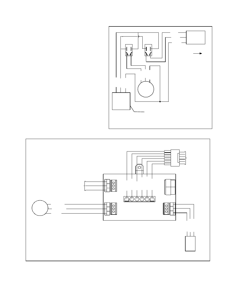
13.
Connect pump power cord to terminals of
electrical box as shown in wiring
Diagrams. See Figures 7 or 8.
14.
Close electrical box and securely tighten
lid of electrical box.
15.
Bundle pump power cord with other
cords using ribbon ties.
16.
Reconnect power and water.
17.
Test new pump for proper operation.
18.
Replace cool pads.
19.
Installation complete.
Black
White
Ground
Single Speed
Harness
TO MOTOR
PUMP
AC
POWER
Fan
Switch
W
h
it
e
*
B
la
c
k
*
B
la
c
k
W
h
it
e
G
ro
u
n
d
Pump
Switch
Ground
Cordset
Figure 7
Single Speed Wiring Diagram
Black*
White*
Ground
To
Motor
2
G
re
e
n
3
R
e
d
4
O
ra
n
g
e
6
B
la
c
k
5
O
ra
n
g
e
1
B
lu
e
Pump
To
Switches
G
ro
u
n
d
B
la
c
k
W
h
it
e
A
C
P
o
w
e
r
C
o
rd
s
e
t
Figure 8
Variable Speed Wiring Diagram
G
ro
u
n
d
* : When wiring Little Giant Pumps, (part # 6422-0612, 6422-0614, and 6642-0615) the
Black and White wires are Blue and Tan, respectively. Compare with ‘Kits’ list on page 1.
* : When wiring Little Giant Pumps, (part # 6422-0612, 6422-0614, and 6642-0615) the
Black and White wires are Blue and Tan, respectively. Compare with ‘Kits’ list on page 1.