Warning – Cub Cadet 20HP Z-Force 44 User Manual
Page 18
18
g.
To replace the blade reverse the above
process and tighten nut to 100-120 lb ft.
Note:
Add a small amount of multi-purpose
grease to the bolt threads to avoid corrosion
and galvenic action.
WARNING:
Never mow with dull blades! Blades that are
bent should be replaced! The cutting blades
are sharp and can cause severe injury. Wrap
the cutting surface of the blade with a rag to
avoid injury.
3.
Sharpening the Blade:
a.
Set the parking brake.
b.
Clean any debris from the blades. Keep
blades sharp and free of build up at all
times.
c.
Sharpen blades evenly at the original 30°
angle to maintain balanced cutting blades.
Do not sharpen the underside of the
blades. Use a electric blade sharpener, a
conventional electric grinder or a hand file
to sharpen the blades.
d.
Replace any blade with severe nicks or
dents that cannot be removed by filing.
e.
Check the balance of the blade after
sharpening by placing it on a blade bal-
ancer. Do not use un-balanced blades.
f.
If the blade dips on one end, file stock off
of the cutting surface on that end.
Note:
Blades that cannot be easily bal-
anced—REPLACE.
4.
Changing the Blade Drive Belts:
a.
Set the parking brake. Remove ignition key
and both spark plug caps.
b.
Unscrew the wing nuts from the deck cov-
ers and remove both covers.
c.
Using a 3/8" socket breaker bar or socket
ratchet insert the drive end into the 3/8"
square opening in the lower idler arm
assembly and push the idler arm counter-
clockwise. While holding the idler arm
back, loosen the blade drive belt from the
pulley and slide the belt away from the pul-
ley.
d.
Remove tension of the PTO belt by moving
the belt tensioning rod. Loosen the belt
retaining bolt.
e.
Pull the tensioner pulley away from the belt
and remove the PTO belt then remove the
blade drive belt.
f.
Reverse the process to install the belt.
Note:
When replacing belts do not over-
tighten. Adjust the idler pulley so that a ten-
pound pull with a spring scale between two
pulleys deflects the belt about 1/2".
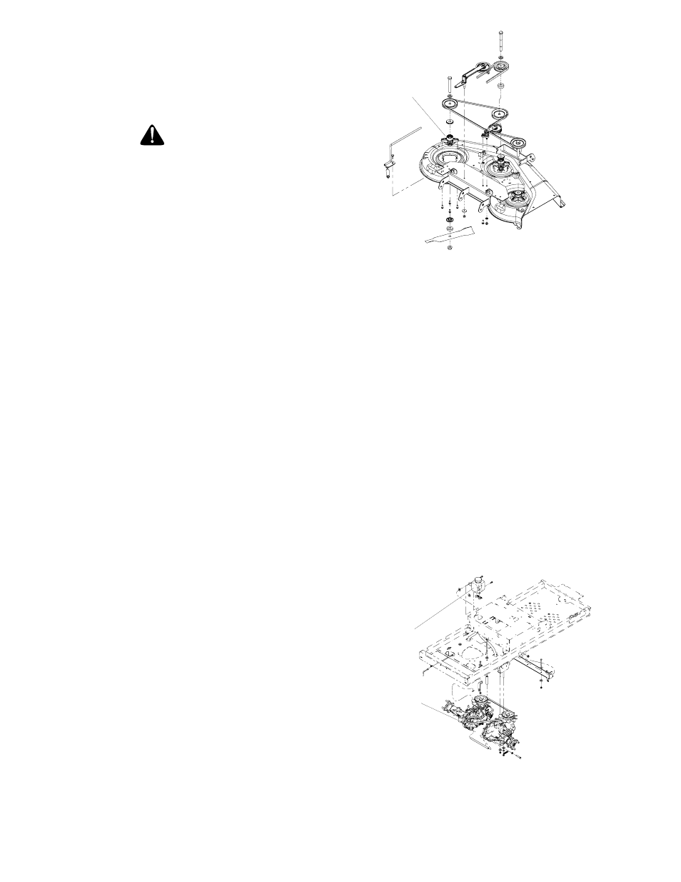
5.
Figure 8
Spindle
Changing the Spindle Assembly
a.
Jack up the front of the mowing deck about
one foot and block it in that position.
b.
Make sure the blade clutch is disengaged.
c.
Remove the deck cover.
d.
Remove the drive belts. (See 3. Changing
Blade Drive Belts.)
e.
Remove the cutter blade. (See 2. Chang-
ing a Blade.)
f.
Using a wrench or socket ratchet remove
four hex nuts, and the four hex head cap
screws. Remove the spindle assembly.
g.
Reverse the process to install the spindle
assembly.
C.Hydrostatic Drive System
1.
Your zero turn riding mower is equipped with
dual integrated hydrostatic pumps, motors, and
planetary gear reduction transaxles. The fluid
level in the expansion tank must be maintained
at 1/2” to 1” above the bottom of the tank.
See Figure 9.
Hydrostatic
Transaxles
Figure 9
expansion tank
Note:
See Maintenance Schedule, Section E,
page 23.