System board layout – Dell OptiPlex 980 (Early 2010) User Manual
Page 12
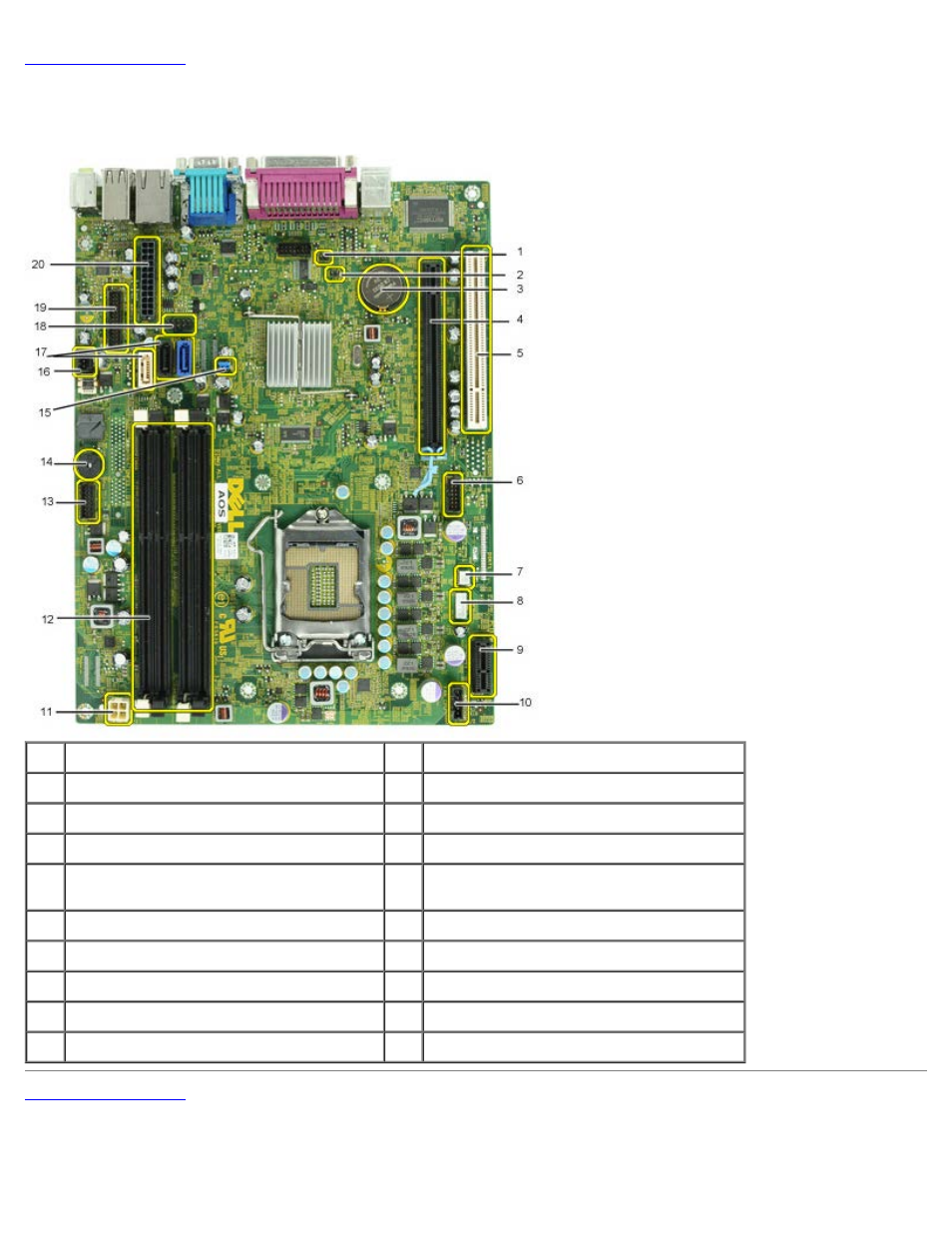
System Board Layout
Dell™ OptiPlex™ 980 Service Manual—Small Form Factor
1
service mode jumper (Service_Mode)
2
RTC reset jumper (RTCRST)
3
battery socket (BATTERY)
4
PCI Express x16 card connector(SLOT1)
5
PCI card connector (SLOT2)
6
internal serial card connector (Serial2)
7
thermal sensor connector (THRM3)
8
speaker connector (INT_SPKR)
9
PCI Express x1 wireless card connector
(PCIE_WLS1)
10 fan connector (FAN_CPU)
11 power connector (12V POWER)
12 memory module connectors (DIMM_1-4)
13 front panel connector (FRONTPANEL)
14 internal buzzer (BEEP)
15 password jumper (PSWD)
16 intruder connector (INTRUDER)
17 SATA drive connectors (SATA0-2)
18 internal USB connector (INT_USB)
19 front I/O connector (FIO)
20 power connector (MICRO_PWR)
See also other documents in the category Dell Computers:
- Inspiron 530 (2 pages)
- OptiPlex 755 (82 pages)
- OptiPlex 755 (45 pages)
- OptiPlex 755 (248 pages)
- OptiPlex 755 (622 pages)
- OptiPlex 755 (528 pages)
- OptiPlex 760 (76 pages)
- OptiPlex 760 (203 pages)
- OptiPlex 745 (428 pages)
- OptiPlex 745 (212 pages)
- OptiPlex 745 (360 pages)
- OptiPlex 780 (89 pages)
- OptiPlex 780 (10 pages)
- OptiPlex 780 (74 pages)
- OptiPlex 780 (80 pages)
- OptiPlex 780 (73 pages)
- OptiPlex 780 (40 pages)
- OptiPlex 780 (14 pages)
- OptiPlex GX620 (221 pages)
- OptiPlex GX620 (294 pages)
- OptiPlex GX620 (338 pages)
- Inspiron 530 (226 pages)
- OptiPlex 960 (Late 2008) (16 pages)
- OptiPlex GX260 (100 pages)
- OptiPlex GX260 (235 pages)
- OptiPlex FX160 (Late 2008) (132 pages)
- OptiPlex FX160 (20 pages)
- OptiPlex FX160 (Late 2008) (20 pages)
- OptiPlex 210L (258 pages)
- OptiPlex 210L (150 pages)
- OptiPlex 210L (130 pages)
- OptiPlex 210L (128 pages)
- OptiPlex 210L (300 pages)
- OptiPlex 320 (140 pages)
- OptiPlex 320 (132 pages)
- OptiPlex 320 (312 pages)
- OptiPlex 320 (266 pages)
- OptiPlex 320 (356 pages)
- OptiPlex 320 (44 pages)
- OptiPlex GX240 (86 pages)
- OptiPlex GX240 (283 pages)
- OptiPlex GX240 (298 pages)
- OptiPlex GX240 (182 pages)
- OptiPlex GX240 (144 pages)
- OptiPlex GX240 (121 pages)