Centro 5000AS User Manual
Page 20
1 8
6
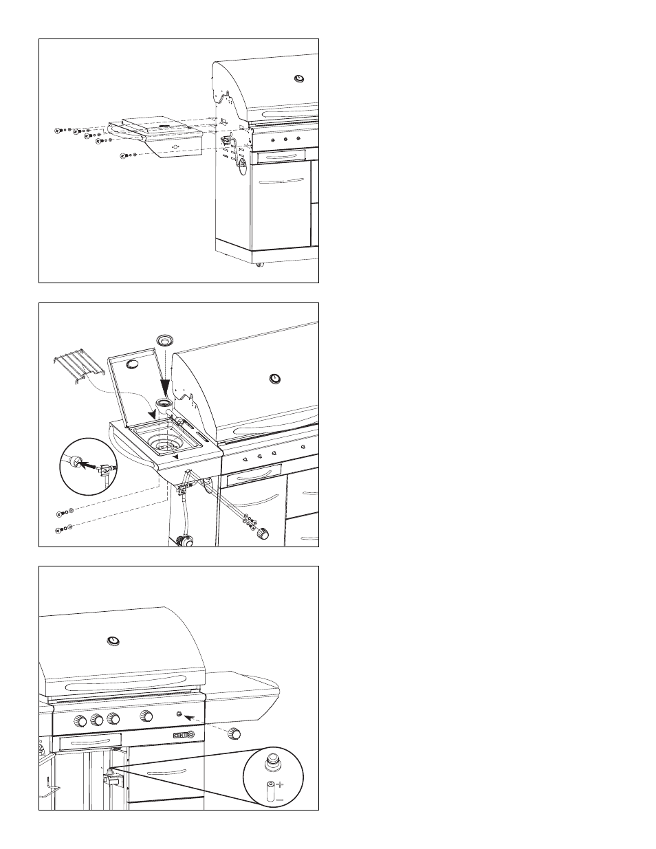
Unscrew igniter cap and place “AA” battery into Igniter (HI) with
positive end (+) facing outward. Screw igniter cap onto igniter as
shown. Attach the control knob (EB) to the valve stem.
5
Push the side burner valve stem and mount it by using screws and
washers included on the valve bracket, threading through the side
burner control panel. Push the knob (EB) onto the valve s tem wi th
the whi te l ine on the knob pointing upwards. Insert the side burner
(FF) into the frame as shown. Gently slide the burner tube over the
orifice of the valve. Place the side burner grate (FG) as shown.
4
Assemble the side burner shelf assembly (F) to the upper left side
panel (CA) by using hardware No. 1, 2, 3 (x3) and No. 4, 5, 6 (x2).
Assemble the side shelf assembly (G) to the right side panel (CB)
using same hardware as above.