Accessory kit to use, Installation procedure – Cisco 1800 Series User Manual
Page 7
11-7
Cisco 1800 Series Routers (Modular) Hardware Installation Guide
OL-5876-03
Chapter 11 Installing and Upgrading Internal Modules in Cisco 1800 Series Routers (Modular)
Modules Internal to the Cisco 1841 Router
Caution
When you install an AIM, always wear an ESD-preventive wrist strap, and ensure that it makes good
contact with your skin. Connect the equipment end of the wrist strap to the metal part of the chassis.
Caution
Handle AIMs by the edges only. AIMs are ESD-sensitive components and can be damaged by
mishandling.
Accessory Kit to Use
Some AIMs are provided with multiple accessory kits that contain different configurations of mounting
hardware. Mounting hardware for the Cisco 1841 router consists of two machine thread metal standoffs,
two machine thread metal screws, and one plastic standoff.
To install an AIM2-CUE-K9 or an AIM2-APPRE-104-K9, use the snap-fit blue standoff, the two hex
standoffs, and the two M2.5 screws found in mounting kit 69-1870-01. You can discard the remaining
parts.
For all other AIM module installations, use the hardware found in mounting kit 69-1316-01.
Installation Procedure
To install the AIM, perform the following steps. You need a number 2 Phillips screwdriver or flat-head
screwdriver to complete this procedure.
Step 1
Find the metal standoff attachment locations on the system board near the AIM connector, indicated by
a star pattern, as shown in
.
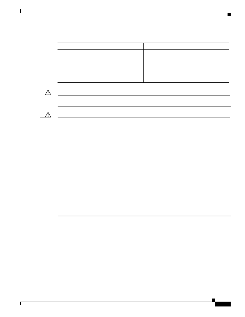
Table 11-1
AIMs Supported on Cisco 1841 Router
Cisco Part Number
Type
AIM-CUE=
Unity Express
AIM2-CUE-K9
Unity Express
AIM2-APPRE-104-K9
AXP—Application eXtension Platform
AIM-IPS
Intrusion Prevention Systems
AIM-VPN-EPII-PLUS
VPN Encryption