Cable Electronics e labs SW808HD User Manual
Page 29
Matrix Switching System—Instruction Manual
Page 25
APPENDIX – Matrix Switch Communication Protocol
The RS-232/RS-485 communications are half-duplex with variable byte count packets.
For RS-232, the matrix switch operates as a DCE device and therefore can be
connected using a straight cable to a DTE device such as a computer. The RS-232
connector is a DB-9 female. For RS-485, a discrete wiring connector is provided for
custom connection to any RS-485 equipment. For full details on connecting to the
matrix switch refer to the User Manual.
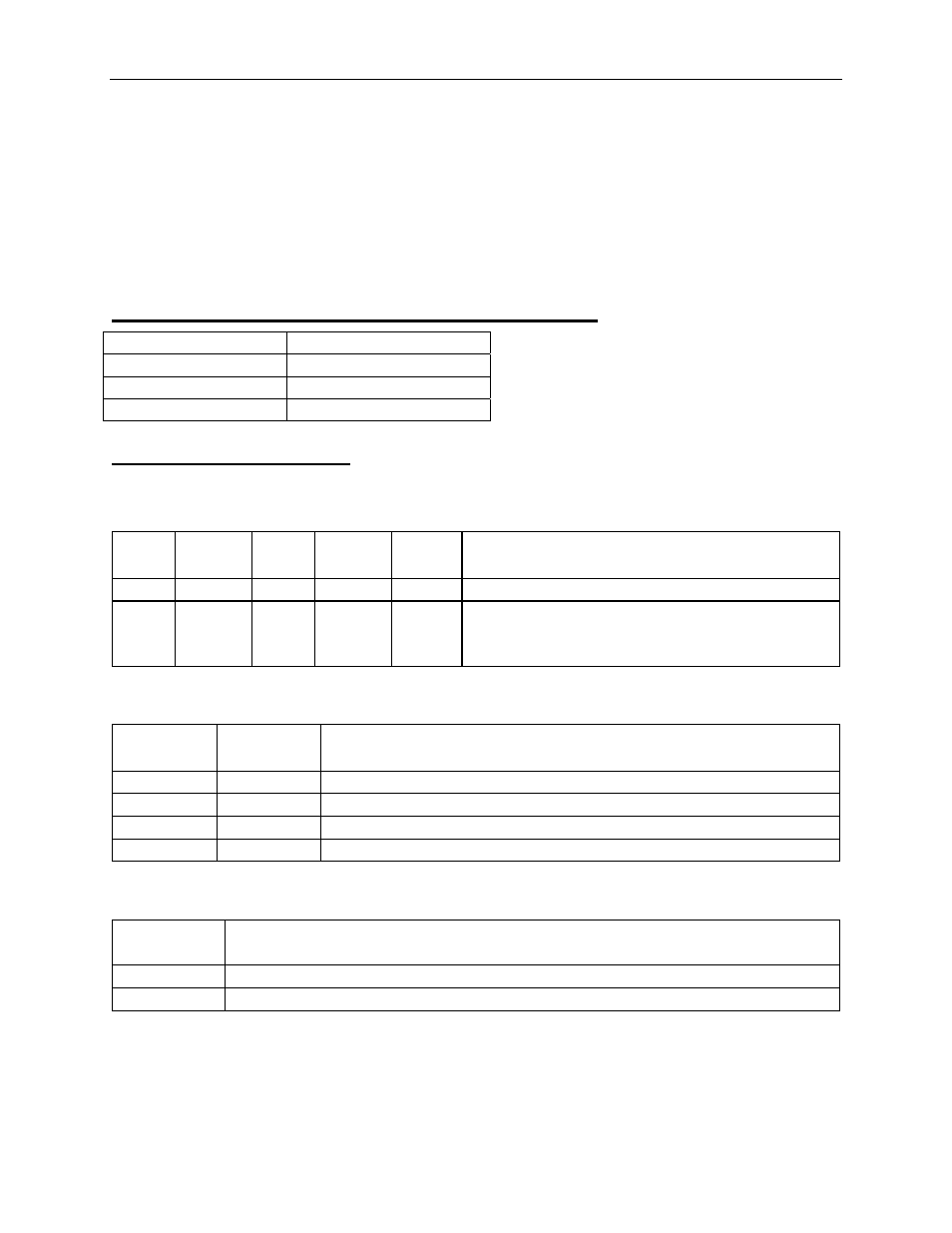
Default Communication Settings – 9600, N, 8, 1
Baud Rate
9600
Parity None
Data Bits
8
Stop Bits
1
DIP Switch Description
SW1-SW5: Machine ID (address)
0=ON, 1=OFF
SW1 SW2 SW3 SW4 SW5
Notes
0
0
0
0
0
Address for RS-232/RS-485 Master only
0
~
1
0
~
1
0
~
1
0
~
1
1
~
1
Addresses for Slave devices
SW6-SW7: RS-485 TX/RX Terminating Resistor
0=ON, 1=OFF
SW6 SW7
Notes
0 0
Resistor
ON
1 1
Resistor
OFF
1 0
Invalid
0 1
Invalid
SW8: RS-232/RS-485 Master or RS-485 Slave
0=ON, 1=OFF
SW8 Notes
0
RS-485 Slave Device
1 RS-232/RS-485
Master