Baumer ISI35 User Manual
Page 9
e
n
g
lis
h
ISI34, ISI35
www.baumer.com
9
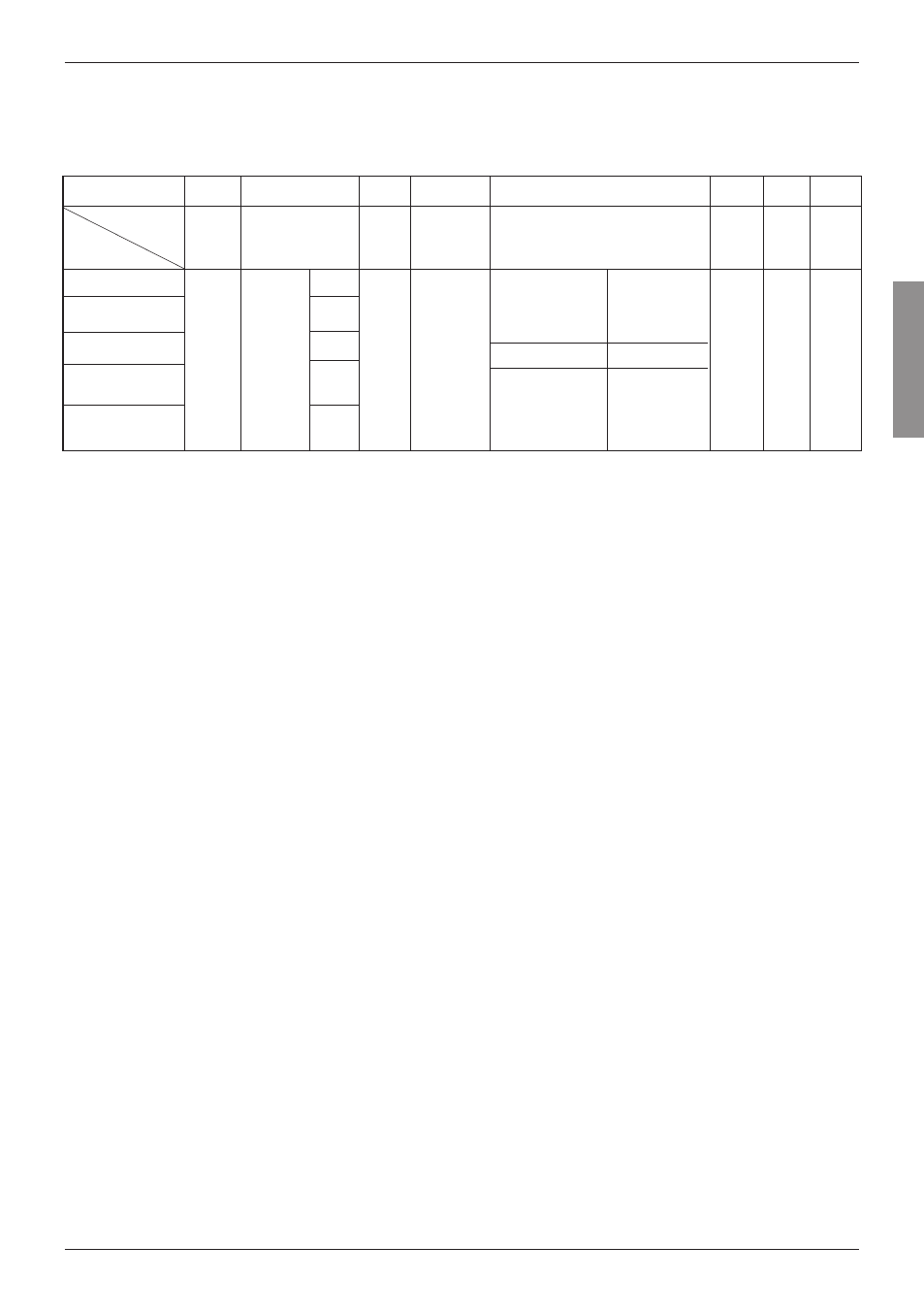
Input specifications, terminal assignment and adjustable time ranges (DC versions)
The time range is set via a control input (screw terminal 5).
Screw terminal
No. 1
No. 2
No. 3
No. 4
No. 5
No. 6
No. 7
not active
=
99999 h 59 m
contact with
GND
=
99999,99 h
ISI34.010AX01
ISI34.011AX01
ISI35.010AX01
ISI35.011AX01
no
f
un
ct
io
n
Ti
m
er
E
na
bl
e
In
pu
t
NPN
PNP
NPN
PNP
R
es
et
i
np
ut
N
PN
N
PN
r
es
et
k
ey
lo
ck
in
g
in
pu
t,
C
on
ta
ct
w
ith
G
N
D
, k
ey
f
re
e
not active
=
9999 h 59 m 59 s
contact with
GND
=
9999999,9 s
G
N
D
=
0
V
D
C
ba
ck
lig
ht
(
–
)
Screw terminal 1: no function
Screw terminal 2:
Timer Enable Input: time measurement as long as the input is
active
NPN:
active for low level
Input resistance:
approximately 1 MOhm
Low level:
0 ... 0,7 V DC
High level:
3 ... 30 V DC
PNP:
active for high level
Input resistance:
approximately 100 kOhm
Low-level:
0 ... 0,7 V DC
High-level:
4 ... 30 V DC
Screw terminal 3:
Reset input:
active for negative edge contact input /
Open Collector NPN (switching at 0 V DC)
Low level:
0 ... 0,7 V DC
High level:
3 ... 30 V DC
Min. pulse duration: 50 ms
Input resistance:
approximately 2,2 MOhm
Screw terminal 4:
Electrical locking of the reset key Contact input / Open Collec-
tor NPN (switching at 0 V DC)
Low level:
0 ... 0,7 V DC
High level:
3 ... 5 V DC
Input resistance:
approximately. 2,2 MOhm
Input not active:
Reset key locked
Input active (contact with GND):
Reset key unlocked
Designation
Model
INP A
INP B
Reset
Reset
Enable
Time range (Mode)
GND
BL
–
No. 8
BL
+
ba
ck
lig
ht
(+
)
Table 2
Screw terminal 5:
Time range switching (Mode) contact input / Open Collector
NPN (switching at 0 V DC)
Low level:
0 ... 0,7 V DC
High level:
3 ... 5 V DC
Input resistance:
approximately. 2,2 MOhm
Function:
see table 2
Remark
If the time range is changed during operation, the device must be
reset, otherwise the counting value will not be reproducible.
Screw terminal 6:
Common GND connection for all inputs
Screw terminal 7:
(–) external power supply for the backlight option
Screw terminal 8:
(+) external power supply for the backlight option
(24 V DC ±20 %, 50 mA)