Baumer ISI35 User Manual
Page 10
ISI34, ISI35
10
www.baumer.com
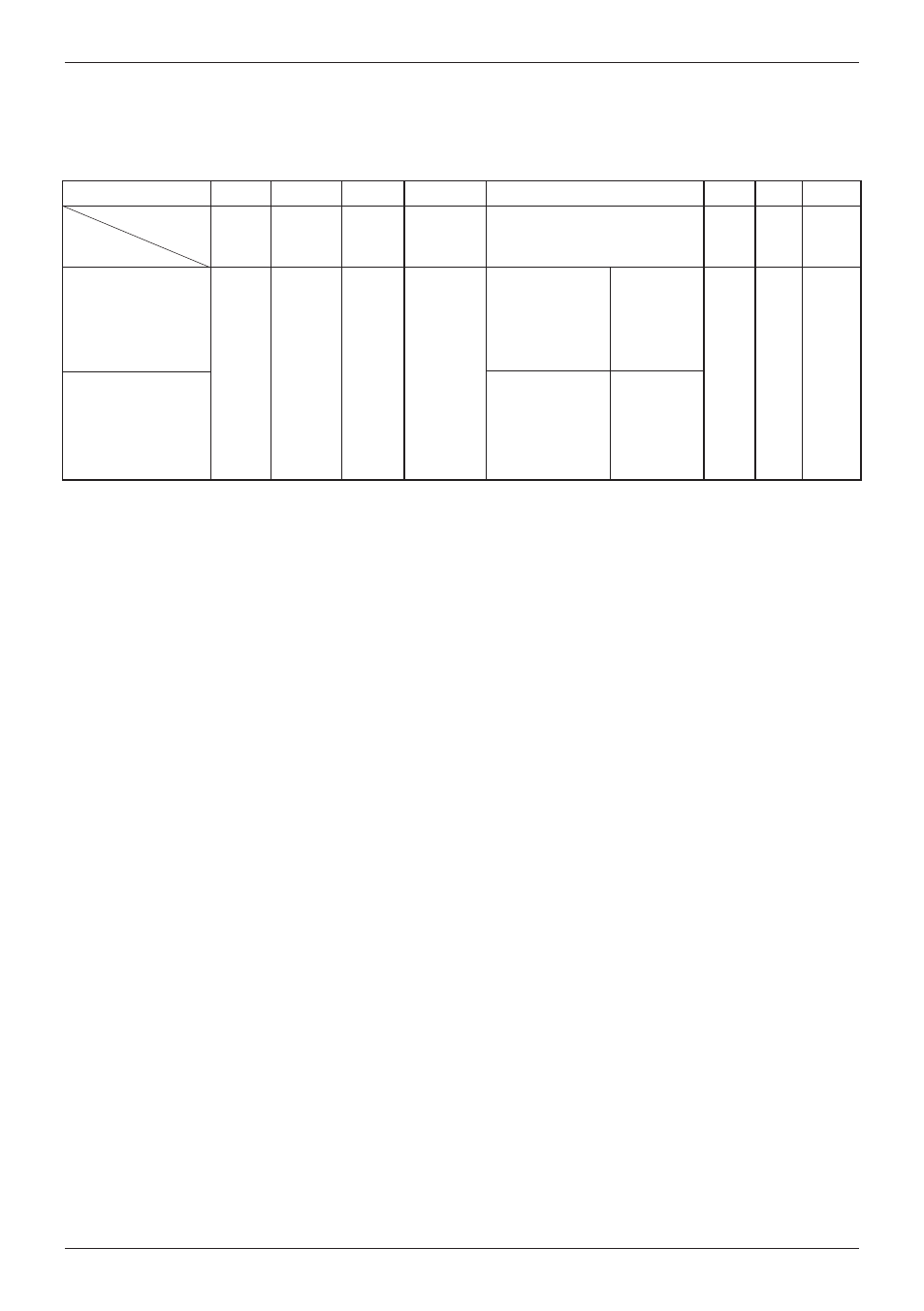
Input specification, terminal assignment and adjustable time ranges (AC versions)
The time range is set via a control input (screw terminal 5).
Screw terminal
No. 1
INP A
AC/DC
No. 2
No. 3
INP B
AC/DC
No. 4
No. 5
No. 6
No. 7 No. 8
ISI34.013AX01
ISI35.013AX01
Ti
m
er
E
na
bl
e
In
pu
t
A
C
/D
C
C
om
m
on
c
on
ne
ct
io
n
fo
r
IN
P
A
an
d
IN
P
B
Reset
Enable
N
PN
r
es
et
k
ey
lo
ck
in
g
in
pu
t,
C
on
ta
ct
w
it
h
G
N
D
. k
ey
f
re
e.
not active
=
99999 h 59 m
not active
=
9999 h 59 m 59 s
G
N
D
=
0
V
D
C
B
ac
kl
ig
ht
in
g
(
–
)
B
ac
kl
ig
ht
in
g
(
+
)
Screw terminal 1:
Timer Enable Input: time measurement as long as the level at
this input is high.
Optocoupler input
10 ... 260 V AC/DC
galvanic isolation, active for
high signal
Low level:
0 ... 2 V AC/V DC
High level:
10 ... 260 V AC/DC
Input resistance:
approximately 160 kOhm
Screw terminal 2:
Common AC/DC, common connection for the optocoupler inputs
(screw terminals 1 and 3)
Screw terminal 3:
Reset input:
active for high level.
Optocoupler input:
10 ... 260 V AC/DC galvanic isolation,
active for high signal
Min. pulse duration: 16 ms
Max. frequency:
approximately 30 Hz
Low level:
0 ... 2 V AC/V DC
High level:
10 ... 260 V AC/DC
Input resistance:
approximately 160 kOhm
Screw terminal 4:
Electrical locking of the reset key Contact input / Open Col-
lector NPN (switching at 0 V DC)
Low level:
0 ... 0,7 V DC
High level:
3 ... 5 V DC
Input resistance:
approximately 2,2 MOhm
Input not active:
Reset key locked
Input in contact with GND:
Reset key unlocked
Screw terminal 5:
Time range switching (Mode)
Contact input / Open Collector NPN
(switching at 0 V DC)
Low level:
0 ... 0,7 V DC
High level:
3 ... 5 V DC
Input resistance:
approximately 2,2 MOhm
Function:
see table 3
Remark:
If the time range is changed during operation, the device must be
reset, otherwise the counting value will not be reproducible.
Screw terminal 6:
Common GND connection for screw terminal 4 (reset key
locking input) and screw terminal 5 (time range switching).
Screw terminal 7:
(–) external power supply for the backlight option
Screw terminal 8:
(+) external power supply for the backlight option
(24 V DC ±20 %, 50 mA)
designation
Model
Common
AC/DC
Time range (Mode)
GND
BL
–
BL
+
re
se
t
in
pu
t
A
C
/D
C
Table 3
contact with
GND
=
99999,99 h
contact with
GND
=
9999999,9 s