Periodic testing – Cooper Lighting ELPS502 User Manual
Page 4
3. Test wiring for correctness with continuity checks and also for unwanted grounds with
insulation resistance tester.
4. Allow the ELPS to charge under line power for 72 hours before initiating any testing of
the emergency operation of the lights.
D. Complete Installation
1. Install CID101 corrosion inhibitor device (supplied loose in ELPS50). Recommended
location is on the bottom wall between “Main Power On” pilot light and 1" NPT tapped
hole. Refer to CID101 instructions for installation.
2. Close cover and securely tighten all cover bolts and nuts to 30 ft. lbs. torque making
certain that no cover bolts are omitted. Use only bolts supplied with the enclosure.
NOTE: ELPS units have two stud bolts located at diagonally opposite corners of the
body to aid in positioning cover.
DO NOT depress the push-to-test pushbutton until after the ELPS has been powered
for 72 hours. The emergency battery requires 72 hours to fully charge. The indicating
light will illuminate steadily (no pulsing) when the ELPS is fully charged.
3. Test emergency lighting system for proper operation:
a. Turn on power to designated disconnect switch.
b. Turn on designated disconnect switch and observe:
• “Main Power ON” indicating pilot light should be operating.
• EVLA12 emergency light(s) should be “OFF”.
c. Press “Push-to-Test” indicating push button switch and observe:
• “Main Power ON” light should be “OFF”.
• EVLA12 emergency light(s) should be “ON”.
4. Lock designated disconnect switch “ON” to prevent unauthorized persons from turning
system “OFF”.
5. Adjust EVLA12 emergency light(s) for the desired direction of illumination & lock into
position using 1-5/8” open-ended wrench & torquing to 58 lb.-ft. See Figure 2.
E. Remote Mounting EVLA12 Emergency Light Only
1. Attach the EVLA12 to a Cooper Crouse-Hinds EABC36 or EABL36 1" NPT outlet box.
2. Secure this assembly to the mounting surface with ¼ inch bolts or lag screws of the
required length (not supplied).
3. Refer to Table 1 on page 6 for conductor recommendations.
4. Refer to Sections B for aiming adjustments and section C for Conduit Connections and
Wiring.
PERIODIC TESTING
Article 700 of the National Electrical Code states that, “Systems shall be tested
periodically on a schedule acceptable to the authority having jurisdiction to assure their
maintenance in proper operating condition”. It also states that, “A written record shall be
kept of such tests and maintenance”.
In the absence of periodic testing requirements by a local authority, the following
recommendations from the NFPA 101 (2003) Life Safety Code are strongly recommended:
1. Monthly: Operate “Push-to-Test” switch and keep depressed for a minimum of 30
seconds. Observe that emergency lighting fixtures are on full brightness for the full
time. Record the test on the maintenance record card. Maintenance Record Card is
provided in instruction sheet envelope.
2. Annually: Shut off power at the distribution panel. Verify that the emergency lighting
fixtures remain “ON” for a minimum of 1-1/2 hours.
NOTE: Leave the designated disconnect switch “ON” during this test so that battery
circuit is not interrupted. We suggest that this test be continued until the power supply
automatically shuts the emergency light(s) off. This will help maintain full battery
capacity.
Record the test on the Maintenance Record Card.
Allow 48 hours charging time before depending on the battery to operate at full
capacity.
Failure to function properly in either test may indicate the need for battery or lamp
replacement.
IF 1510 • 05/06
Copyright © 2006, Cooper Industries, Inc.
Page 4
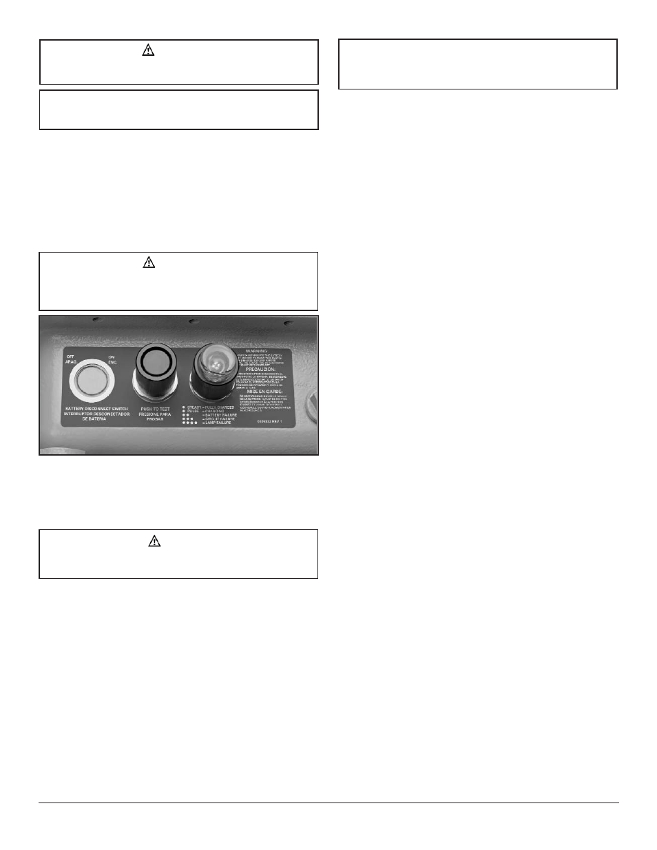
Figure 5. ELPS50 Controls
CAUTION
To avoid explosion, clean both flat joint surfaces of body and cover before closing.
Dirt or foreign material must not accumulate on flat joint surfaces. Surfaces must
seat fully against each other to provide a proper explosion proof seal.
WARNING
To avoid electrical shocks, use fixture only on systems with an equipment
grounding conductor.
NOTE
Unit needs to charge for 72 hours before conducting any tests. Do not disconnect
AC power until unit is fully charged.
NOTE
In Class II and Class III and Simultaneous Presence locations, limit upward
aiming of fixture to a maximum of 30º above horizontal. Greater upward aiming
could lead to excessive dust buildup and dangerous overheating of the dust.
NOTE
A Class I, Division 1 sealing fitting must be installed within 18 inches of the
conduit entry of the ELPS enclosure. Use Chico A or Chico SpeedSeal sealing
compound to seal the conduit entry.