F-16 controls – Dynalco F-16 Frequency Generator/Counter User Manual
Page 2
Azonix-Dynalco, 3690 N.W. 53 Street, Fort Lauderdale, FL 3330 U.S.A.
(954) 739-4300 • Fax (954) 484-3376 • www.dynalco.com • [email protected]
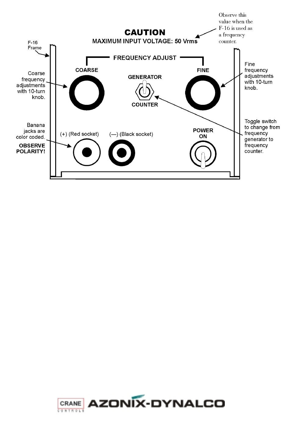
F-16 CONTROLS
CALIBRATION EXAMPLE
Determine setpoint value on an SW-50 Series Speed Switch — on the bench
J
Turn on the F-16.
J
Set the F-16 to a low frequency—below what would be expected to trip that
setpoint.
J
Attach the red F-16 lead to Terminal 3 on the SW-50.
J
Attach the black F-16 lead to terminal 2 on the SW-50.
J
Make sure the F-16 is set to GENERATOR.
J
Slowly increase the frequency on the F-16.
J
Using an ohmmeter across each relay contact, in turn, determine the frequency
at which the relays change state.
Note: An overspeed relay will latch if terminal 4 is not grounded.
Change setpoint value on an SW-50 Series Speed Switch — on the bench
Remove the screws in the access holes for the required setpoint adjustment trim pots.
J
Set the signal generator to the frequency at which the relay should change
state.
J
Using a small, flat blade screwdriver, slowly adjust the trim pot for the
appropriate relay until the relay changes state.
• CW to increase the setpoint value
• CCW to decrease the setpoint value
J
Decrease the frequency, then slowly increase it to verify that the relay trips at
the appropriate point.