Control board illustration – Chamberlain HS670 User Manual
Page 16
16
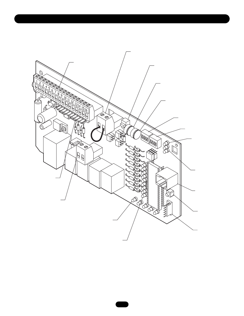
CONTROL BOARD ILLUSTRATION
P R O G R A M M I N G
Relay Drive Troubleshooting LEDs (D6)
Terminal Troubleshooting LEDs (D11)
Connector SAMS (J5)
Connector (J2)
Connector
Aux. Relay Drive
(J3, not used)
Motor Learn
Button
Programming Port
(factory use only)
Limit LEDs
Connector
Main Terminal
Wiring (J1)
Timer to Close
DIP Switch
Master/Second (S4)
Connector
Master/Second (J4)
Diagnostic LED
DIP Switch (S2)
DIP Switch (S1)
Force Adjustment