3start up – CTEK Z4200U SkyRouter User Manual
Page 9
2 March 2014
5
.
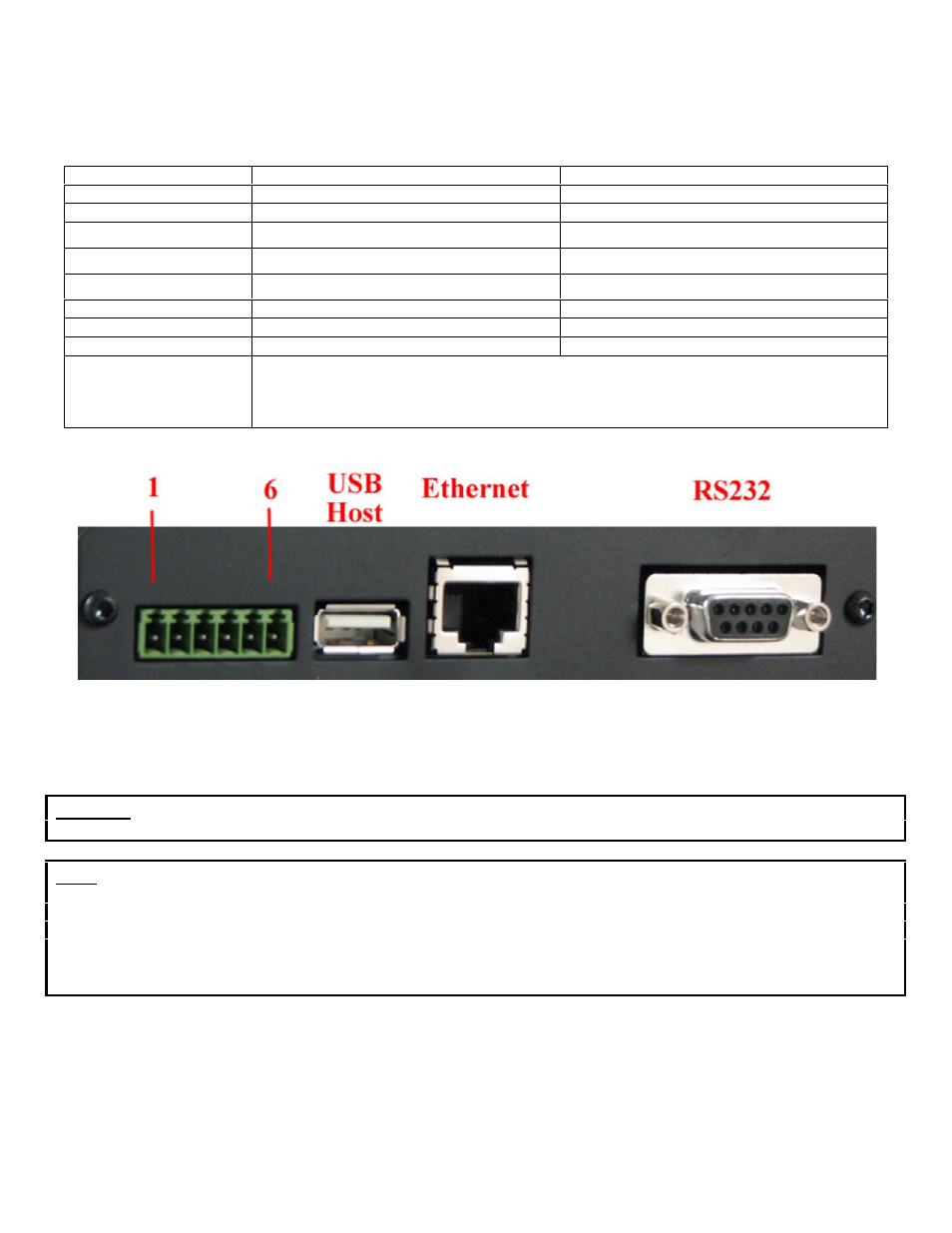
The J1 pin out configuration is as follows:
Terminal Block Pin
JP1 & JP2 (internal) Center to Right
JP1 & JP2 (internal) Center to Left
Pin 1
Din Src – Discrete Input Source
Pin 2
Din – Discrete Input (See Appendix A)
TR- of RS-485 auxiliary serial port
1
Pin 3
Dout Gnd – Discrete Output Ground
Ground of RS-485 auxiliary serial port
2
Pin 4
Dout - Discrete Output
3
TR+ of RS-485 auxiliary serial port
1
Pin 5
Power supply Ground
Power supply Ground
Pin 6
Power supply +12VDC
Power supply +12VDC
Notes
Note 1
Note 2
Note 3
Connect a 120 ohm resistor across pins 2 --> 4 for multi-drop configurations
Available as a third wire ground for use in noisy environments
Discrete output is rated at 200ma @ 24 volts maximum sink current
Figure 3 - Z4200U Connectors
3
Start Up
Warning
– You must connect antenna(s) to the SMA style antenna connectors on the router before turning it on.
Failure to do this could result in erratic start up behavior and could possibly damage the unit.
Note
– Z Series routers ship from the factory with DHCP server enabled. The Default Gateway address for the
unit is 192.168.1.10. The address of the web-based administration is also 192.168.1.10. The default source of DNS
is set to “Acquire From Wireless Network.” After you have activated your unit, enabled the WAN connection, and
restarted the unit the SkyRouter will obtain DNS addresses from the wireless network and populate those
addresses on the Ethernet Interface page. From this point on any changes to DNS addressing detected by the
wireless network connection will be displayed on the Ethernet Interface screen and will be the source of DNS
name resolution.