Cooper Instruments & Systems DTW 400 Digital Torque Tester / Screwdriver User Manual
Page 2
CF132 DTW 400/405
2
11/12
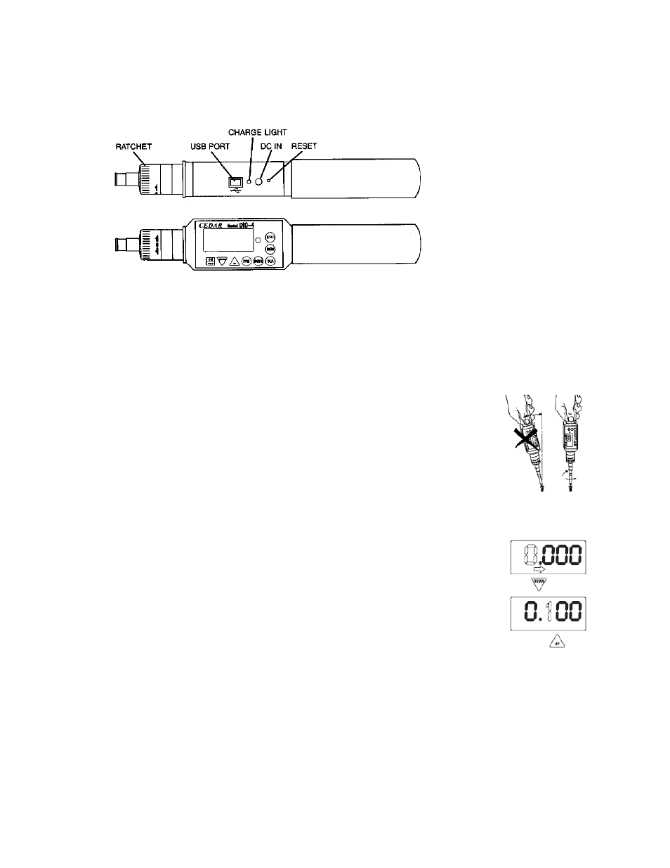
Ratchet Operation CW, CCW and fixed positions
USB virtual COM port Send data to computer via USB cable
Charge Light lights when charging, off when complete
DC IN AC charger/adapter receptacle
RESET System reset button
GENERAL OPERATION
1. Press and hold MODE for one second to select from the following Measuring Modes.
REAL TIME – Displays torque transients (no output or indicator)
PP Mode – Peak, captures peak torque) peak data output, PP appears on the display)
PD Mode – First Peak, capture first peak value, (peak data output, PD appears on the display)
C Mode – Continuous RS-232 out display and output torque transient (180 data/sec., C appears on the
display.)
2. Insert Phillips tip into the screwdriver.
3. To select ratchet operation turn the ratchet one click CW or CCW from the center
position. To disable ratcheting, turn it so the semi circle is in the center position.
4. Press the CLEAR button on the display unit to zero the display. Insert the screwdriver
tip into the screw, hold perpendicularly (not at an angle) and turn to measure.
5. After measuring, press CLEAR to zero the display for the next test.
PROGRAMMING
Press POWER to turn on. Press PRG for one second. The display shows “HI” and then
the High setpoint value. This confirms the tester is ready for the following programming
steps:
1. High Setpoint (HI)
After “HI” is displayed and the High setpoint value, press DOWN (6) to move the
numeric place and press UP (7) to select values i.e. 50.0 for 50.0 lf-in, then press
PRG (8) to enter.
2. Low Setpoint (LO)
After High value is entered, “LO” is displayed, then the Low setpoint value. Press
DOWN to move the numeric place and press to select values, then press PRG to
enter.
3. Peak Down Minimum (PdLO)
After Low value is entered, “PdLO” is displayed and then the PdLO value. Press
DOWN to move the numeric place and press to select values, then press PRG to enter.
PdLO sets a minimum torque value for Peak Down mode. For example if “PdLO” value is set at 5.0 lbf-in,
only a reading over 5.0 lbf-in will be measured in Peak Down mode.
4. Continuous Data Output Minimum (CLO)
After Peak Down value is entered, “CLO” is displayed, then the CLO value. Press DOWN to move the
numeric place and press to select values, then press PRG to enter.
CLO sets the start and stop trigger points for continuous data output. When torque reaches the CLO value,
the tester starts to output data and stops if torque falls below the value. NOTE: the display does not show
any value below the CLO minimum.