Introduction, Block diagram, 3 absolute maximum ratings – Calyx S1A0051 - FET Driver for Class-D PWM Amp User Manual
Page 3: Digital & analog co., ltd. (rev. 1.0) -3
S1A0051 FET Driver for Class-D PWM Amp
Digital & Analog Co., Ltd. (Rev. 1.0) -3-
1. INTRODUCTION
◎ FET (GATE) Driver for CLASS-D Amp
◎ Schmitt Triggered Input
◎ Totem-Pole Structured Output Stage
◎ Four Independent Power MOSFET Gate Drivers
◎ Operating Voltage : 10 ~ 12V (Single Power),
± 5.0V – ± 6.0V(Dual Power)
◎ High Performance for Switching Characteristics
○ Typically 15ns for rising/falling time with 1nF load
○ Typically 20ns for propagation delay time with 1nF load
◎ BiCMOS Technology / 16 ETSSOP
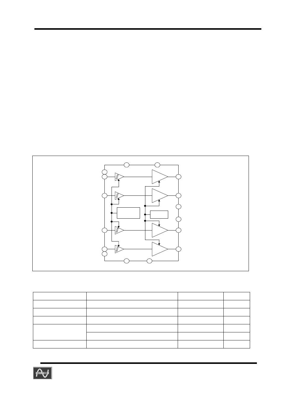
2. BLOCK DIAGRAM
1
2
3
16
4
Driver1
15
Driver2
14
R eference &
Logic Power
Supplier
5
6
7
1/2 Bias
Driver3
Driver4
8
9
10
11
12
13
VCC
NC
NC
VSS
VC C34
VCC12
VSS12
VSS34
3 ABSOLUTE MAXIMUM RATINGS
Symbol Parameter Value
Units
VCC Driver
supply
voltage
13.5
V
Tstg
Storage Temperature
-40 – 125
°C
Topr
Operating Temperature
-25 – 75
°C
Human Body Model, All pin
2000
V
Electro-Static
Discharge
Machine Model, All pin
200
V
Pd Power
Dissipation
1000 mW