Installation – BE Pressure supply 80 Gallon Air Compressor AC5080B3 User Manual
Page 4
Installation
SELECTING A LOCATION
Select a well lit indoor area with plenty of space for proper
cooling air flow and accessibility. Locate the compressor at
least 15 inches (38 cm) from walls, and make sure the power
supply is clearly identified and accessible.
Temperature. Ideal operating temperatures are between 40º
and 100ºF (4º and 37ºC). If temperatures consistently drop
below 32ºF (0ºC), install the compressor inside a heated
building. If this is not possible, you must protect safety/relief
valves and drain valves from freezing.
CAUTION!
NEVER
operate in temperatures below 15ºF (-9ºC) or
above 125ºF (52ºC).
Humid Areas. In frequently humid areas, moisture may form
in the pump and produce sludge in the lubricant, causing
running parts to wear out prematurely. Excessive moisture is
especially likely to occur if the compressor is located in an
unheated area that is subject to large temperature changes.
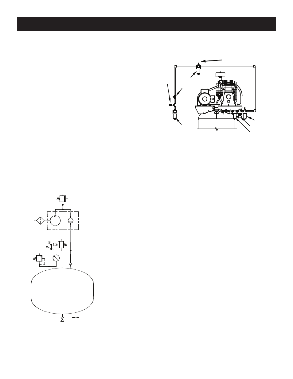
PNEUMATIC SCHEMATIC
80-Gallon Tank
Safety Relief
Valve
34796 Pump (Item #
459231
)
34798 Pump (Item #
459241
)
Unloader
Pressure
Switch
Safety
Relief
Valve
Note:
Pressure switch automatically activates the unloader.
SLOPE
TRAP
REGULATOR
FILTER/TRAP
LUBRICATOR
TRAP
OUTLET
VALVE
00855
INSTALLING DISCHARGE PIPING
CAUTION! If you will be using synthetic lubricant, all
downstream piping material and system components
must be compatible. Refer to suitable list on page 6.
General Requirements. The piping, fittings, etc. must
be certified for at least 4 times the working pressure. Use
hard-welded, threaded steel or copper pipes and cast
iron fittings that are certified safe for the compressors
discharge pressure and temperature. DO NOT USE PVC
PLASTIC. Use pipe thread sealant on all threads, and
make up joints tightly to prevent air leaks.
Main Air Distribution Line. The main compressed air
distribution line should be of sufficient size to minimize
the pressure drop between the air supply and the point
of use. Slope the piping downward in the direction of
air flow to aid in the removal of condensation at all drain
points along the line. The piping must be as short and
direct as possible, and adequately braced.
Drip Legs. A drip leg is a pipe extending downward
from the main line to collect condensation. Drip legs
should be at the lowest points in the air line and at any
point where the leg goes around an obstruction. A drain
valve should be installed at the bottom of each drip leg.
Drop Legs. A drop leg is piping originating from the
main air distribution line that feeds air to an outlet for
tools or other air operated devices. Drop legs are taken
off the top of the main line so that condensation does
not easily flow into them. Drop legs should be designed
so that the air outlet comes off the side of the drop leg,
rather than the bottom. By doing this, the condensation
which is carried from the main line collects below the
outlet and prevents moisture from entering the tool or
device using the air. A drain valve should be installed on
the bottom of each drop leg.