Instruction manual, Microphone preamplifier, Appendix f – Aphex 1788A Premium Eight Chan Mic Pre User Manual
Page 47: Appendix f: word clock cabling, Figure 1 principle of 75 ω matched transmission, Figure 2 75 ω transmission loop-through jacks
Page 46
MICROPHONE PREAMPLIFIER
Page 47
Instruction Manual
APPENDIX F
APPENDIX F: WORD CLOCK CABLING
Transmission Systems
There are basically two systems in use for distributing word
clock by coaxial lines: 75
Ω matched, and unmatched with
unspecified impedance. We sometimes call the unmatched
method “brute force”. You’ll see why as you go through
this tutorial.
Matched Coaxial Transmission
This is by far the better way to send pulse shaped wave-
forms over a long distance. Coaxial cable is manufactured
to several standard impedance characteristics. The most
common are 50 and 75 ohms (
Ω). 50Ω cable has tradition-
ally been popular around radio transmission apparatus,
but television has long adopted 75
Ω cable to carry video
signals. Industry has also adopted 75
Ω for the lead-in and
internal house wiring for cable TV. More recently, the AES
adopted, by standard AES3-ID 2001, 75
Ω cable for distri-
bution of digital audio.
For practical purposes, transmission line theory need not
be studied at great length. The basic idea is very simple.
To create a matched transmission line, you terminate both
ends of the line by a resistance equal to the line’s own
characteristic impedance.
This configuration causes all the power launched from
the sending end to be absorbed at the receiving end. The
useful bandwidth of the line is maximized under these con-
ditions, and the pulse waveform is best preserved.
That is not to say the pulse waveform won’t undergo some
degradation. All matched transmission lines have losses,
especially at high frequencies. When the cable exceeds
a certain length, depending on the cable’s quality, cable
equalization may be required to recover additional band-
with. Nevertheless, a general rule is that matched transmis-
sion lines will always have better bandwidth and less jitter
than unmatched lines of equal length.
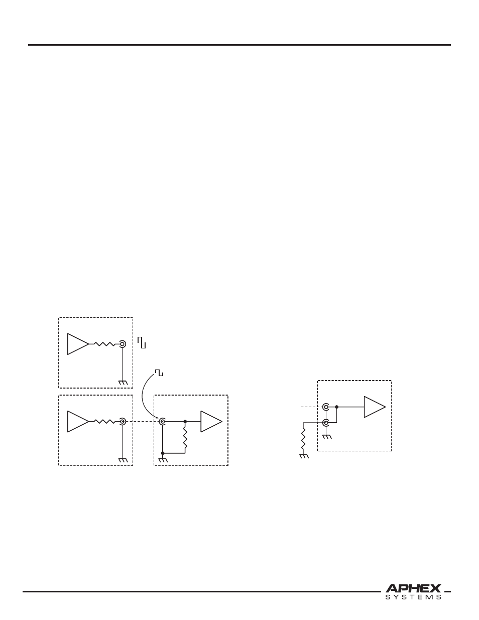
It should be noted from figure 1 that when a matching line
driver is not loaded by the line, its output voltage rises by
double. This is something to take into account when mea-
suring or specifying word clock output levels.
A slight revision of figure 1 is shown in figure 2. The inter-
nal termination resistor is replaced by a “loop-through”
jack and an external load adapter. The principle is the
same, but the loop-through jack allows daisy-chaining
of many clock recipients from a single clock source over a
single clock cable. As you could imagine, this can greatly
simplify clock distribution among compatible equipment.
Daisy-Chain Example
Figure 3 expands upon figure 2 to show the principle of
daisy-chaining a matched transmission. Note that only the
last unit in a daisy-chain needs a load adapter to properly
terminate the 75
Ω line.
Unmatched Lines
In the simplest context, an unmatched line
is
one that is
5Vp-p Open Circuit
2.5Vp-p With Termination
75Ω
Load
Termination
75Ω
Source
Termination
75Ω
Coax
Line
Clock
Transmitter
Clock
Receiver
75Ω
Source
Termination
Clock
Transmitter
Figure 1
Principle of 75
Ω Matched Transmission
75Ω Coax Line
Input Jack
75Ω
Load
Adapter
Loop-Through Jack
75Ω Clock
Receiver
Figure 2
75
Ω Transmission Loop-Through Jacks