0 introduction, 0 controls & indicators – Aphex DUAL RPA 500 User Manual
Page 4
Page 6
Page 7
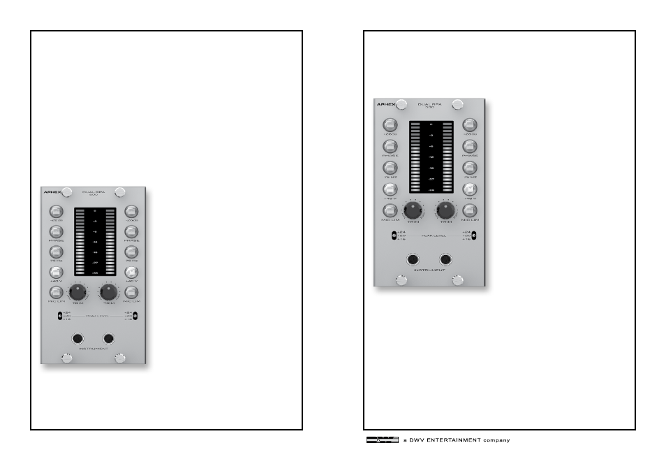
The DUAL RPA 500 is a two-channel microphone preamp featuring
a two channel reflected plate amplifier tube mic pre. It takes up
two slots in your receiving frame. The preamp features electronically
balanced inputs and outputs and uses a discrete, solid-state, trans-
formerless front end carefully crafted for extremely low noise and
high common mode rejection. The back end features a 12AT7 tube
and the Aphex patented RPA circuit. The unique and stable RPA
tube circuit retains the tube’s transconductance and grid character-
istics while at the same time creating a much more efficient amplifier
stage that runs on low power supply voltages.
2.0 INTRODUCTION
3.4 -26dB PAD
When the input signal is clipping
the preamp with the input trim
control turned all the way down,
the -26dB pad can be engaged to
provide more headroom.
3.5 PHASE
The Phase button will invert the
input signal 180 degrees. Using
two microphones on the same
source can cause phase problems.
Reversing the phase of one of the
microphone signals will often clear
up the issue.
3.6 75Hz HIGH PASS FILTER
Engaging the 75Hz HPF will roll off
all the freqencies below 75Hz at
18dB/octave. It’s a good idea to
use the HPF when recording voices
or instruments that don’t have
much low frequency content. Only
capturing the relevant frequencies
will provide a cleaner mix later on.
3.7 48V PHANTOM POWER
Condenser microphones require power to function. Sometimes
a microphone will use internal batteries, but usually the required
power is provided by the mic pre. Turning on the Phantom Power
will send power through the cable to power the microphone. Be care-
full though, as ribbon microphones and some older dynamic micro-
phones can be damaged or destroyed by phantom power.
3.0 CONTROLS & INDICATORS
3.1 TRIM CONTROL
The Trim control boosts the input
signal from +26dB to +65dB.
3.2 INPUT METER
This 20 segment input meter pro-
vides visual confirmation of the input
signal level. The top three LEDs of
the meter are red. When the input
signal reaches the top red LED, the
input signal will clip.
3.3 OUTPUT LEVEL SWITCH
The output level can be set to +16dB,
+20dB and +24dB. You will need to
know the maximum input level of
the next device in the audio chain to
set this properly. Most professional
audio devices can handle a +24db
input signal without issue.
However, some inexpensive computer audio interfaces have a
maximum input level of less than +16dB. Most also offer a -20dB
pad to address these kind of issues.