Assembly instructions – Antennacraft ST3 User Manual
Page 2
Acceptable Types of Antenna Installations
1.
Tripod: Use a 3-foot or 5-foot tripod bolted to a roof
or other sturdy mounting surface. Guy wires are not re-
quired.
2.
Chimney Mount: Use heavy-duty chimney mounts,
straps, or brackets attached to the chimney or to a wall.
For safety, limit mast assembly to 10-foot or smaller.
Guy wires are not required.
3.
Eave or Wall Mount: Use heavy-duty brackets at-
tached to wood or masonry. The complete installation
must be able to support the antenna assembly, plus
wind pressure. For safety, limit mast assembly to 10-
foot or smaller. Guy wires are not required.
4.
Guyed Mast: Use a heavy duty telescoping antenna
mast (not included) and guy wires (not included).
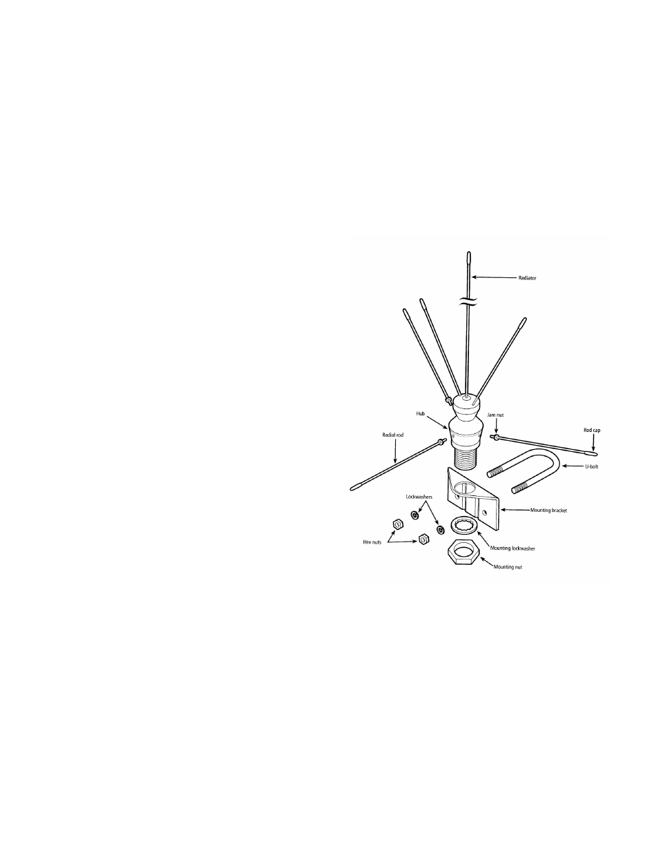
Assembly Instructions
1. Assemble the radial rods by screwing one jam nut on
the threaded end of each rod and placing one radial rod
cap on the opposite end of each rod.
2. Hand-tighten each radial rod into the hub of the radiator
assembly. Then, tighten the jam nut against the hub.
3. Place the radiator rod caps on the ends of the radiator
rods.
4. Attach the assembled antenna to the mounting bracket
with the mounting lockwasher and the mounting nut. Be
sure to tighten the mounting nut securely.
Installation Instructions
1. Route coax cable (not included) from your receiver to
your antenna location.
2. Attach the antenna to the mast (not included) using the
U-bolt, hex nuts, and lockwashers. Be sure to tighten all
nuts securely.
3. Connect the coax cable to the antenna using a PL-259
connector (not included).
4. Fasten the coax cable to the mast with fasteners (avail-
able at your local electronics store) to avoid strain on
the cable connections.
5. Mount the mast at a location you have checked for
power line clearance.
6. Ground your antenna. Drive a ½” copper or steel rod
into the ground as close to the antenna base as pos-
sible. Connect an 8-gauge or larger copper or alumi-
num wire (available at your local electronics store) from
the antenna to the ground rod. Use the U-bolt as the
antenna grounding connections point.
7. Attach the warning label to the mast at eye level.
PARTS LIST:
DESCRIPTION ........QUANTITY INCLUDED
Radiator assembly .....................1
Radial rods ................................3
Mounting bracket .......................1
U-bolt .........................................1
Lockwashers..............................2
Hex nuts ....................................2
Jam nuts ....................................3
Mounting lockwasher .................1
Mounting nut ..............................1
Rod caps ...................................6
Warning label .............................1
www.antennacraft.net
12/03/07