Unfolding the implement, Opener operation – Great Plains CTA4000 Operator Manual User Manual
Page 17
15
Section 2 Operating Instructions
2/1/06
CTA4000 Air Drill Implement 160-269M
Great Plains Mfg., Inc.
5.
Install wing lock pins to secure folded wings as shown
in Figure 2-3.
Figure 2-3
Folded Wings Secured
Unfolding the Implement
1.
Remove and store wing lock pins. See Figure 2-4 for
lock-pin storage.
Figure 2-4
Wing Lock Pin in Storage
2.
Check that field/folding selector valve is in folding
position.
3.
Set tractor at low idle speed.
4.
Energize tractor hydraulics and slowly unfold imple-
ment.
5.
Continue to unfold implement only until each wing
gauge wheel rests on ground, then return hydraulic
lever to neutral.
6.
When sections are unfolded, turn field/fold selector
valve to field position.
7.
Unlock openers by turning field/transport selector
valve to field postion.
Opener Operation
The hydraulic system places down pressure on the open-
ers for even soil penetration across the drill–even in
uneven ground.
1.
Lock hydraulic lever forward during field operation for
constant hydraulic flow to openers.
John Deere tractors with Sound-Gard ® Body: Use
lever lock clip, John Deere part number R52667, to
lock lever forward. See your tractor dealer for clip pur-
chase and installation.
John Deere 7000 Series tractors: Rotate valve
detent selector to motor position to lock lever in for-
ward position.
John Deere 8000 Series tractors: Set timer to con-
tinuous. Push lever forward until detent clicks.
Case-IH Magnum tractors: Lock lever forward in
detent position. You may need to turn up detent pres-
sure to its maximum setting. Do not tie hydraulic lever
past detent position with a strap. See your tractor
dealer for hydraulic-system details.
Other tractors: Lock lever forward in detent position.
You may need to turn up detent pressure to maximum
or use a mechanical detent holder to hold lever for-
ward. See your tractor dealer for proper means of pro-
viding constant flow to openers.
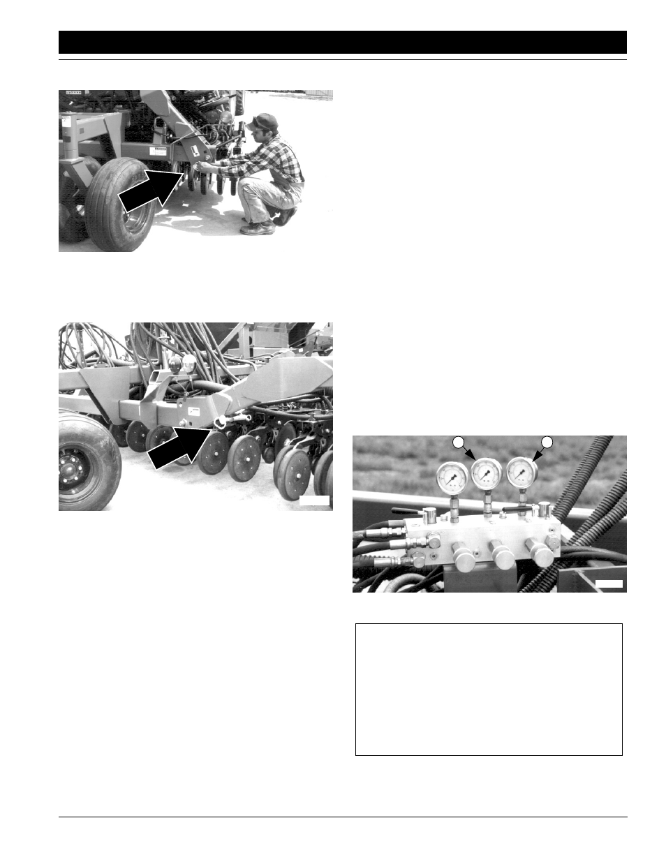
2.
Set opener down pressure. There is one pressure-
control valve for wing sections (1) and one for center
section (2). See Figure 2-5. Initially set down pressure
at 800 psi, then adjust as field condition warrant. For
more information on adjusting opener hydraulic down,
refer to Opener Down Pressure, “Adjustments,” page
19.
Figure 2-5
Pressure Control Valves
17171
17155
17163
1
2
IMPORTANT: Some tractors with load-sensing or con-
stant-flow hydraulics need a bypass valve, Great Plains
part number 810-400C, to operate the CTA4000. Fail-
ure to install the valve can cause major tractor damage.
Contact your Great Plains dealer to order the bypass
valve. Contact your tractor dealer to verify if a bypass is
needed. Before adjusting opener down pressure, set
bypass valve as explained under Load Sensing Hy-
draulics, Preparation and Setup, page 11.