Bleeding marker hydraulics – Great Plains 2410P Assembly Instructions User Manual
Page 5
4/9/2004
113-742M
Great Plains Mfg., Inc.
5
Installation Instructions
With Sequence Valve
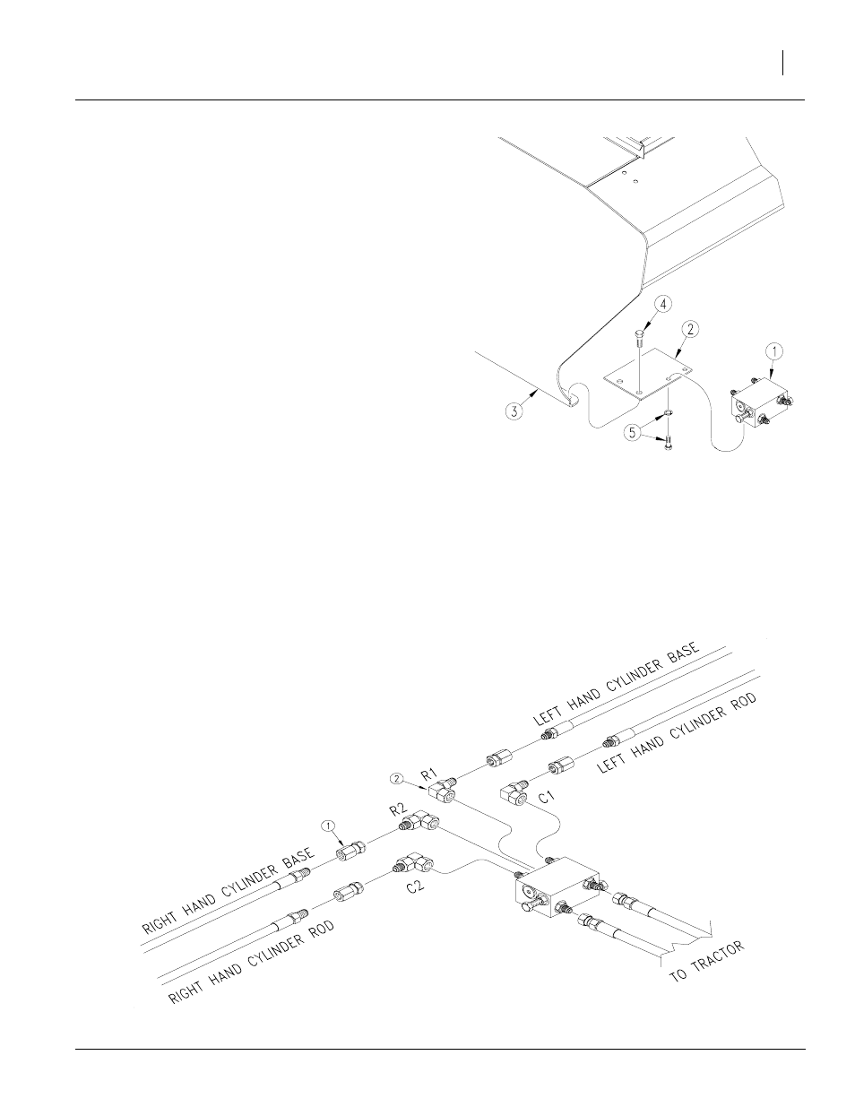
Refer to Figure 6.
1.
Mount sequence valve (1) 810-197C on drill
using mounting plate (2) 113-488D. Bolt plate
to inside end of left-hand-box panel (3) using
one 1/2-inch hex bolt (4). The sequence valve
and mounting plate can be purchased seper
ately from your Great Plains Dealer.
2.
Bolt valve (1) to mounting plate (2) with two 3/
8 x 3/4-inch hex bolts and lock washers (5).
3.
Install elbow fittings in cylinder ports. Discard
adaptor fitting and two needle valves provided
in marker kit.
4.
Use hoses provided to connect valve ports to
cylinders. Refer to Figure 7 for port connec-
tions .(1) 811-440C and (2) 811-169C, dealer
and customer must order these seperately.
5.
Connect your own hydraulic hoses to ports on
front of valve. Route hoses to tractor outlets.
6.
Using orange cable tie, secure plastic hose
label, see Figure 5, to hydraulic hoses near
tractor outlets.
7.
Proceed with "Bleeding Marker Hydraulics"
on page 5.
Bleeding Marker Hydraulics
Figure 6
Sequence Valve Assembly
18416
19209
Figure 7
Hydraulic Hose Connection