Assembly – Great Plains Blockage Monitor Assembly Instructions User Manual
Page 3
3
4/8/04
Air Drill Blockage Monitor 168-258M
Great Plains Mfg., Inc.
Assembly
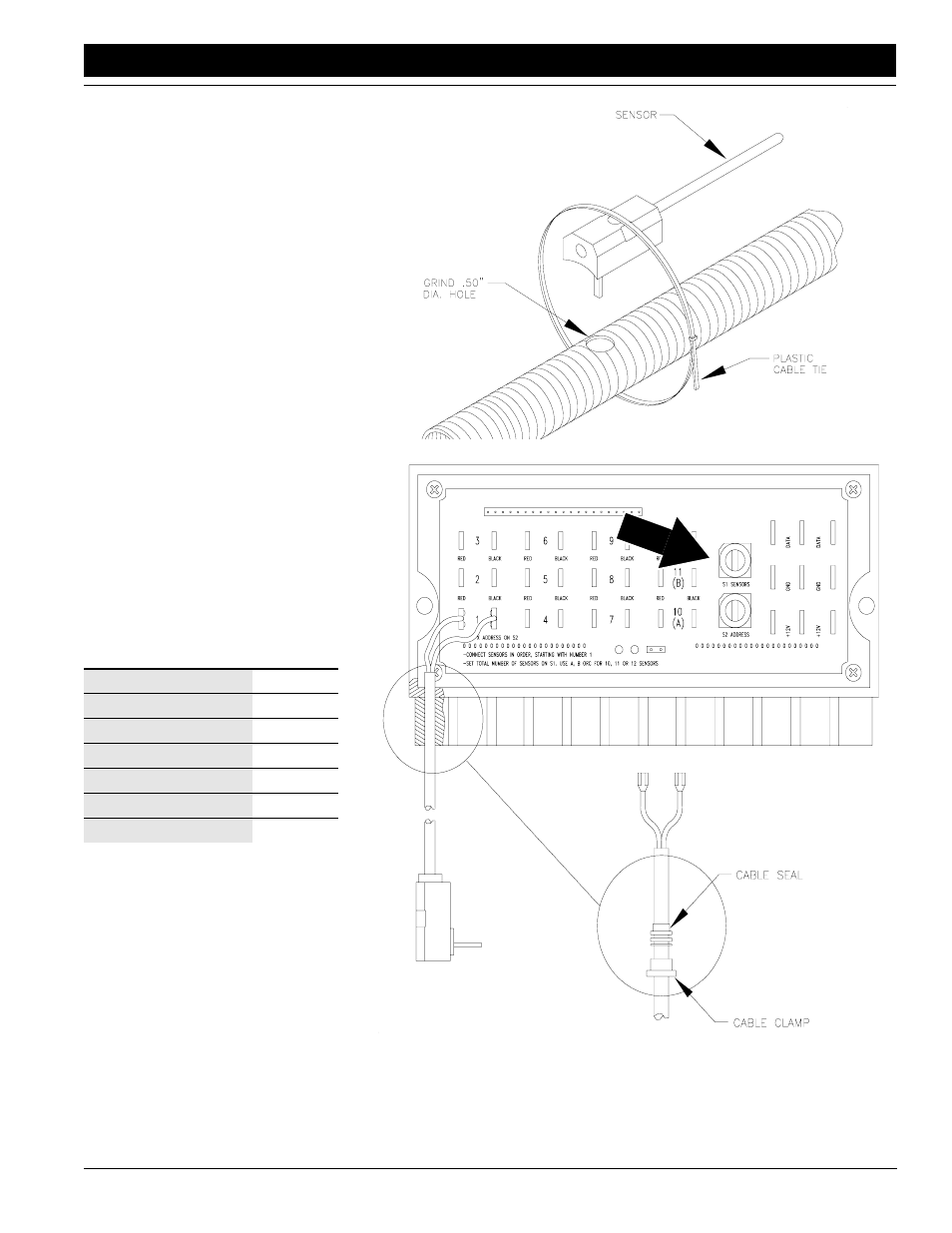
5.
Install sensor number 1 on a second-
ary seed hose. To install, insert sen-
sor pin into 1/2-inch hole and secure
sensor body to secondary seed hose
with a cable tie. Working clockwise
around distribution tower, continue
installing sensors into hoses until all
sensors for tower are installed.
6.
Connect sensors to modules. On
connector panel, find numbered con-
nector pins. Connect lead from sen-
sor 1 to pins marked 1. Connect lead
from sensor 2 to pins marked 2. Pro-
ceed until all senors for tower are
connected to module for that tower.
7.
After connecting sensors to module,
set S1 SENSOR rotary switch on
connector panel. Refer to the follow-
ing table for proper switch setting
Number of sensors con-
nected to module:
S1 SENSOR
Setting
1
1
2
2
3
3
9
9
10
A
11
B
12
C
8.
Repeat steps 3 through 7 for each
implement tower.
18092
18089
- 1200 Parts Manual (210 pages)
- 706NT Material Rate (46 pages)
- 706NT Material Rate (50 pages)
- 2N-2410 Operator Manual (48 pages)
- 2N-2410 Operator Manual (56 pages)
- 12 Series Drills Assembly Instructions (6 pages)
- X-PresS 2006 Assembly Instructions (50 pages)
- TM500 Operator Manual (62 pages)
- 2010HDP Operator Manual (166 pages)
- YP1630F Material Rate (42 pages)
- YP2425 Operator Manual (162 pages)
- 3S-5000 Operator Manual (94 pages)
- 3PYP Operator Manual (188 pages)
- 3N-3010P Assembly Instructions (2 pages)
- 3N-3010 Assembly Instructions (9 pages)
- 3N-3010P Assembly Instructions (9 pages)
- PFH-15 Predelivery Manual (23 pages)
- PFH-15 Operator Manual (46 pages)
- PFH-15 Operator Manual (26 pages)
- P15126 Serial No 12724 (34 pages)
- DVN 8321 Operator Manual (38 pages)
- 3P500 Assembly Instructions (22 pages)
- 3P600 Assembly Instructions (12 pages)
- 605NT Assembly Instructions (8 pages)
- 605NT Assembly Instructions (4 pages)
- CPH-12 Assembly Instructions (3 pages)
- YP1625A-2420 24 Row 20-Inch Quick Start (6 pages)
- 8323 FCF Predelivery Manual (124 pages)
- P13937 (20 pages)
- 3323 DH Parts Manual (114 pages)
- YP3025-1820 25 Series 18 Row 20 Inch Quick Start (5 pages)
- CF500 Operator Manual (38 pages)
- PFH-15 Assembly Instructions (30 pages)
- 3500TM Parts Manual (106 pages)
- 1800TM Parts Manual (158 pages)
- YP2425A-2470 24 Row 70 cm Quick Start (5 pages)
- Simba Culti Press Operator Manual (38 pages)
- RU1999 Parts Manual (58 pages)
- 3N-30P Assembly Instructions (10 pages)
- 2510HDP Operator Manual (180 pages)
- YP1220 Parts Manual (136 pages)
- 3P500 Material Rate (68 pages)
- YP2425-3620 36 Row 20 Inch Quick Start (5 pages)
- 706NT Operator Manual (53 pages)
- 706NT Operator Manual (22 pages)