Setting fertilizer drive range, Range: front sprocket, Range: rear sprocket – Great Plains 3S-4010HDF Material Rate User Manual
Page 17: Changing range sprockets, Range: front sprocket range: rear sprocket
Great Plains Mfg., Inc.
15
01/29/2009
196-522B
Setting Fertilizer Drive Range
Refer to the Fertilizer Rate Chart on page 31 to find the
correct Range sprocket size for your drill’s row spacing
and the target (or adjusted) application rate.
Ranges overlap. Choose a Range so that the Transmis-
sion (Driver/Driven) pairing is further from the end of that
Range chart, reducing the chances that a Transmission
adjustment might also require a Range change.
Change fertilizer range requires changing one or two
sprockets per drill section, per the table at right. An idler
is loosed and re-engaged for any sprocket change.
Range: Front Sprocket
The two Front range sprockets (
) are perma-
nently installed, and are exchanged by sliding left and
right on the shaft. Remove the spring-clasp polymer
spacer
to permit sliding, and re-insert it as instructed
below to keep the Front and Rear sprockets aligned.
Range: Rear Sprocket
There are three possible Rear
range sprockets (
,
,
). Remove a lynch pin (not shown) to change
this sprocket.
The two rear range sprockets not presently in use are
stored on the Driven Transmission shaft
below the Rear range shaft.
There are also main box Drive Type sprockets stored
here, but the tooth counts are unique to each drive. Tooth
counts are stamped into the face of each sprocket.
Changing Range Sprockets
1.
Loosen the Range idler.
2.
If the Front sprocket needs changing:
remove the polymer spacer
;
slide both sprockets to where spacer was; and,
re-clasp spacer on the other side of sprocket pair.
3.
If the Rear sprocket needs changing:
remove the pin from the rear and storage
shafts;
remove the current Rear sprocket
;
remove the next sprocket from storage;
place the next sprocket on the Rear shaft and re-pin;
return other sprockets to the lower shaft and re-pin.
4.
Re-engage the Range idler for
1
⁄
4
in (6.4mm) slack in
the top chain span.
5.
If this is the final Range setting, after calibration,
repeat step 1 through step 4 for the center and left
drill sections.
In our example, two settings are near the adjusted rate:
LOW Range 24T/12T Transmission, or
HIGH Range, and 12T/21T Transmission.
Use the HIGH Range setting, as it is further from the
end of the chart, allowing easier adjustment.
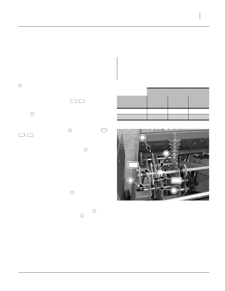
Fertilizer Range
Sprockets
Low
High
Ultra
High
Front
15T
41T
41T
Rear
60T
47T
16T
Figure 7
Range Sprockets: Center Section
15T Front Engaged (Low Range)
28179
3
4
2
41T
15T
1
16T
47T
60T
4