Great Plains 148-152P Assembly Instructions User Manual
Page 2
5/5/2009
Great Plains Mfg., Inc.
Dual Marker Option
2
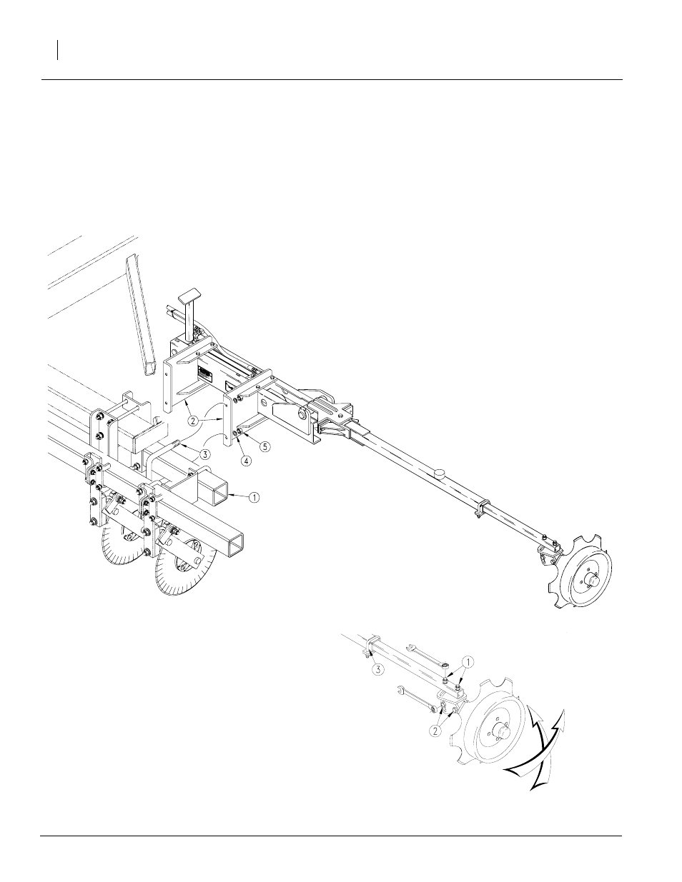
Refer to Figure 2
3.
U-bolt mounting brackets (2) to rear coulter tool-
bar (1) as coulter spacing allows. Use 5/8-11 X 4
X 5 1/4 u-bolts (3), 5/8 lock washers (4), and 5/8-
11 hex nuts (5) to secure mounting brackets (2) to
coulter toolbar (1).
4.
Check to make sure shear bolt is oriented to-
wards front of hitch.
5.
Complete steps 3 and 4 to attach opposite marker
and mount to rear coulter toolbar.
24486
Figure 2
Marker Assembly
Disk Adjustment
Refer to Figure 3
The agressiveness and the mark left by the disk
may be changed by two methods:
a.
Disk Angle: To change the angle of cut,
loosen the two vertical bolts (1) in the
marker arm and rotate the disk assembly.
Retighten bolts.
b.
Disk Tip: To change the tip of the disk,
loosen the two horizontal bolts (5) in the
pivot adjustment. Rotate the disk assem-
bly and retighten. The marker width ad-
justments are made by loosening the
marker tube u-bolt (3) and sliding it in or
out to the desired width. Retighten the u-
bolt.
14061
Figure 3
Disk Adjustment