Figure 5 cage screen case: remove old sensor, Figure 6 cage screen case: install new sensor, Re-install fan screen – Great Plains YP1625 Installation Instructions User Manual
Page 4
Great Plains Mfg., Inc.
4
Fan Sensor Kit
168-045M
10/09/2006
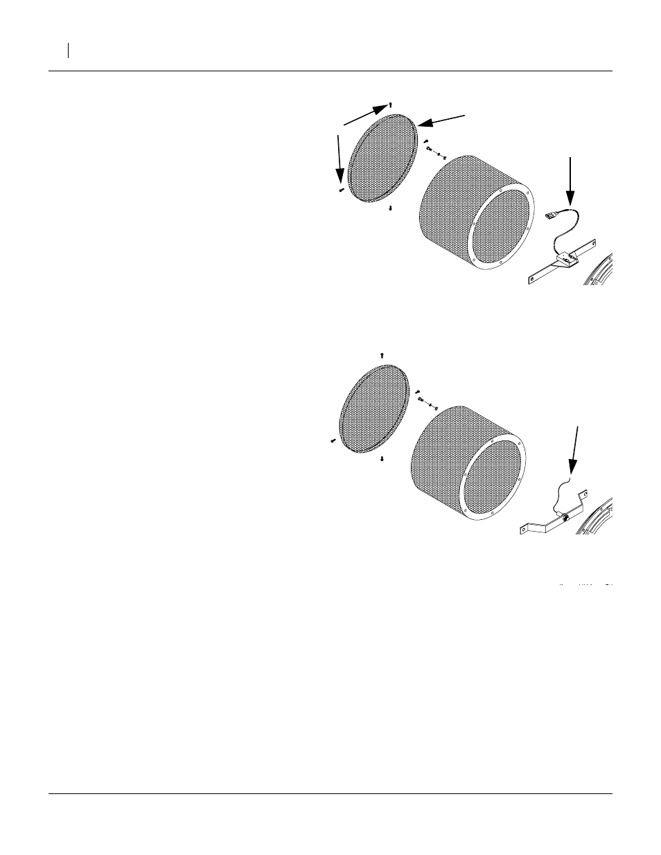
Sensor Installation (Cylindrical Cage Fan Screens Only)
Remove Screen and Sensor Bracket
The screen cage has a flat end cap screen
➃
and cylin-
drical body screen. Although the illustration depicts cage
removal, it is usually only necessary to remove the cap.
4.
Remove and save the end cap screws
➄
. Keep
these separate from the bracket screws removed in
the next step, as they may not be identical (or have
washers).
5.
Remove and save the two
1
⁄
4
-20x
3
⁄
4
in screws and
fender washers retaining the sensor bracket. The old
bracket and sensor
➅
are not re-used, and may be
discarded.
Install New Sensor
6.
Mount new sensor/bracket assembly
➆
with sensor
toward fan, and cable away from fan.
7.
Adjust sensor position for
1
⁄
8
inch. clearance between
tip of sensor and magnet on fan disc. Rotate disc
slowly by hand to verify clearance.
8.
Tighten one or both nuts to lock-in final sensor place-
ment.
9.
Re-install screws and washers retaining sensor
bracket.
Re-Install Fan Screen
10. {step not required for cage screens}
11. {step not required for cage screens}
12. Route the sensor cable through the existing hole
used by the old cable.
13. {step not required for cage screens}
14. {step not required for cage screens}
15. Re-attach screen cap and tighten screws.
Figure 5
Cage Screen Case:
Remove Old Sensor
25115
➄
➅
➃
Figure 6
Cage Screen Case:
Install New Sensor
25116
➆