Caution, Danger, Bleeding the hydraulic system – Great Plains 1205-NT Assembly Instructions User Manual
Page 5
5
5/5/09
1205-NT Folding Marker Option 113-549M
Great Plains Mfg., Inc.
Bleeding The Hydraulic System
!
CAUTION!
Escaping fluid under pressure can have sufficient force to pene-
trate the skin. Check all hydraulic lines and hoses before apply-
ing pressure. Fluid escaping from a very small hole can be
almost invisible. Use paper or cardboard, not body parts, to
check for suspected leaks. If injured, seek medical assistance
from a doctor that is familiar with this type of injury. Foreign
fluids in the tissue must be surgically removed within a few
hours or gangrene will result.
NOTE: JIC fittings do not require high torque. JIC and o-
ring fittings do not require sealant. Always use liquid pipe
sealant when adding or replacing pipe thread fittings. To
avoid possible danger of cracking hydraulic fittings from
overtightening, Do not use plastic sealant tape.
NOTE: Check the hydraulic fluid level in the tractor reser-
voir and fill to the proper level before starting this proce-
dure. Add fluid to the system as needed. A low reservoir
level may draw air back into the system, causing jerky or
uneven cylinder movements.
!
DANGER!
Keep all persons clear.
NOTE: The following instructions must be followed to bleed
the markers hydraulic system. The markers must be prop-
erly bled to displace air in the hydraulic system and for the
sequence valve to work properly. Failure to do so could
cause the marker to drop quickly to the ground and cause
damage to the marker voiding the warranty.
Dual Markers
With Sequence Valve
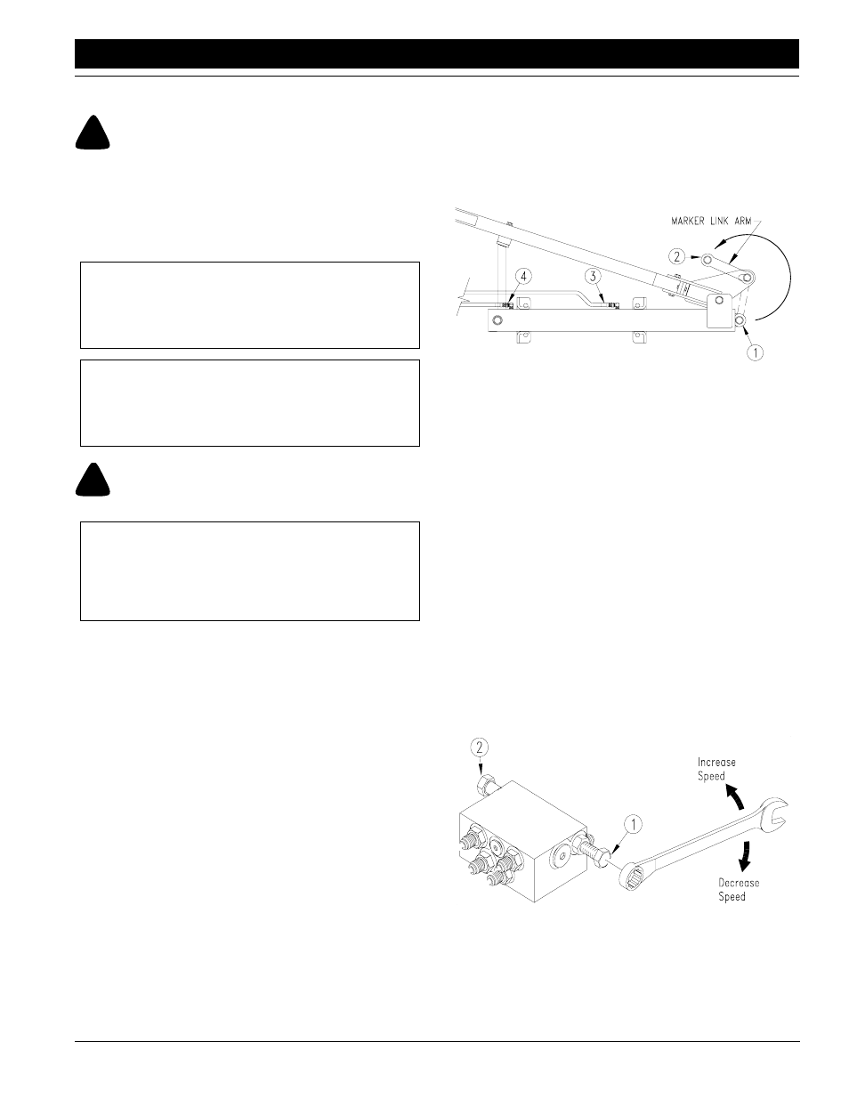
Refer to Figure 5:
1.
The markers should be manually folded into the transport
position when charging the hydraulic system for the first
time. Disconnect the cylinder pin (#1) from the rod end of the
cylinders and the marker link arms (#2) and swing the link
arm up and out of the way.
2.
Connect the hoses to the tractors remote hydraulic outlets.
3.
Loosen the hose hydraulic fittings at the rod end of the mark-
er cylinders (#3). With the tractor at idle speed, slowly work
the tractor remote lever in the direction which would retract
the cylinder. Don't try to retract the cylinder, the goal is to
push the air from the lines leading to the cylinder. This will
only happen on one side which is dependent on which way
the sequence valve is shifted. When the air is expelled and
oil starts being pushed out, tighten the hose connection at
this cylinder.
4.
Slowly work the tractor's remote lever in the same direction
to retract the cylinder. When it is retracted, loosen the hose
fitting at the base end of the same cylinder (#4). With the
tractor at idle speed, slowly work the tractor remote lever in
the opposite direction which should put oil to the cylinder
base port. When the air is expelled and oil starts being
pushed out, tighten the hose connection at this cylinder.
5.
Once again, slowly work the tractor's remote lever in the di-
rection to fully extend the cylinder and hold it there for a few
seconds. This will shift the sequence valve which will allow
you to bleed the opposite cylinder.
6.
Repeat steps 3 through 5 for the other cylinder.
7.
Once the system is bled, operate the tractor's remote lever
several times until both cylinders stop when fully extended
and reconnect the cylinders to the marker link arms.
Bleeding The Marker Cylinder
Figure 5
14021
Refer to Figure 6:
8.
The marker hydraulic system is equipped with needle valves
to control how fast each marker operates. The needle valves
are built into the sequence valve body. There are two hex ad-
justment screws, one for raising, and one for lowering the
markers. The "raise" and "lower" needle valves are identified
by stamped markings in the valve body next to the adjustment
screws. Turn the adjustment screws clockwise to slow the
speed down and counterclockwise to speed it up. Adjust-
ments should be made for safe speeds at operating rpm. Ex-
cessive folding speeds can cause marker damage and may
void the warranty. Be sure to tighten the jam nuts on the hex
adjustment screws to hold the desired settings.
The markers cycle in the following sequence:
1. right up, left up
2. right down, left up
3. right up, left up
4. right up, left down
5. sequence repeats
Sequence Valve, Speed Adjustments
Figure 6
14048