Frame height seeding rate, Adjust drive sprockets set seed-rate handle, Frame height – Great Plains 2515 Operator Manual User Manual
Page 19: Seeding rate
17
Section 3 Adjustments
4/20/05
1515, 2015 and 2515 Three-Point Soybean Machine 173-159M
Great Plains Mfg., Inc.
Frame Height
Drill operating height directly affects the working range of
the drill openers. Initially adjust frame height as explained
under Leveling Drill, Preparation and Setup, page 11.
You can make further adjustments to compensate for field
conditions.
When adjusting the gauge-wheel turnbuckles, remember:
• Lengthening turnbuckles raises drill and allows less
opener down float.
• Shortening turnbuckles lowers drill and allows less
opener up float.
After adjusting gauge-wheel turnbuckles, be sure to level
the drill with top hitch link.
NOTE: Lowering the drill increases the risk of opener
damage on rocks or obstructions.
Seeding Rate
Calibrating the seeding rate requires four steps:
• adjusting drive sprockets,
• setting seed-rate handle,
• positioning seed-cup doors, and
• checking seeding rate.
Refer to the seed-rate charts on page 18. These charts list
proper sprocket sizes and seed-rate-handle settings for
various seeds and seeding rates.
The seed-rate charts are based on cleaned, untreated
seed of average size and test weight. The charts are
based on 9.5L x 15 rib implement tires for 15-foot drills and
11L x 15 rib implement tires for 20- and 25-foot drills.
Many factors will affect seeding rates including foreign ma-
terial, seed treatment, seed size, seed weight, field condi-
tions and tire pressure. You likely will need to make minor
adjustments. Set and check the seeding rate, then read-
just the rate as necessary.
Before setting the seeding rate, rotate the gauge wheels.
Check that seed cups and drive are working properly and
free from foreign material.
Adjust Drive Sprockets
Install drive sprockets for the drive type for your desired
seeding rate.
For correct drive type, refer to seed-rate charts beginning
on page 18. The charts lists drive types as 1, 2, 3 or 4. Re-
fer to the following table for correct-sized sprocket for each
drive type.
Drive Type
Driver
Driven
Speed
Type 1
15 Tooth
47 Tooth
Slowest
Type 2
24 Tooth
36 Tooth
Two Times Faster
Than Type 1
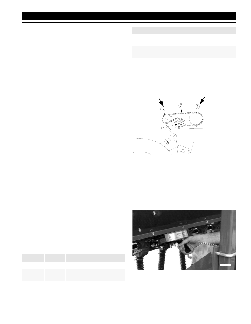
To change drive sprockets, refer to Figure 3-12. Loosen
idler plate and remove drive chain. Remove lynch pins
from shafts and rearrange driver and driven sprockets.
Reroute drive chain over sprockets and idlers as shown in
Figure 3-12. Move idlers into chain so chain has 1/4-inch
slack in its longest span. Tighten idlers.
Figure 3-12
Driver and Driven Sprockets
Set same drive type on both drill sections.
Set Seed-Rate Handle
Position seed-rate handle for each drill box as indicated on
seed-rate chart. One handle is shown in Figure 3-13.
To adjust seed-rate handle, loosen wing nut under handle.
Slide handle until indicator is just past the correct setting,
then move the handle back down to the correct setting.
Retighten wing nut.
Figure 3-13
Seed-Rate Handle
Type 3
24 Tooth
24 Tooth
Three Times Faster
Than Type 1
Type 4
24 Tooth
15 Tooth
Five Times Faster
Than Type 1
Drive Type
Driver
Driven
Speed
Driver
Driven
17669
17618