Danger, Prestart checklist, Hitching tractor to hitch – Great Plains CPH-20 Operator Manual User Manual
Page 9
7
Section 1 Preparation and Setup
12/29/2011
CPH Center Pivot Hitch 148-152M
Great Plains Mfg., Inc.
Section 1
Preparation and Setup
This section will help you prepare your tractor and drill for
use. You must hitch the tractor to the hitch, connect the hy-
draulics to your tractor, hitch the drill to your hitch, and
bleed the hydraulic systems.
Prestart Checklist
1.
Read and understand “Important Safety Informa-
tion,” page 1.
2.
Check that all working parts are moving freely, bolts
are tight, and cotter pins are spread.
3.
Check that all grease fittings are in place and lubricat-
ed. Refer to Lubrication, “Maintenance and Lubrica-
tion,” page 19.
4.
Check that all safety decals and reflectors are correct-
ly located and legible. Replace decals if damaged.
See Safety Decals, “Important Safety Information,”
page 4.
5.
Inflate tires to pressure recommended and tighten
wheel bolts as specified. See “Appendix,” page 24
Hitching Tractor to Hitch
!
DANGER!
You may be severely injured or killed by being crushed between
the tractor and drill. Do not stand or place any part of your
body between drill and moving tractor. Stop tractor engine and
set park brake before installing the hitch bolt.
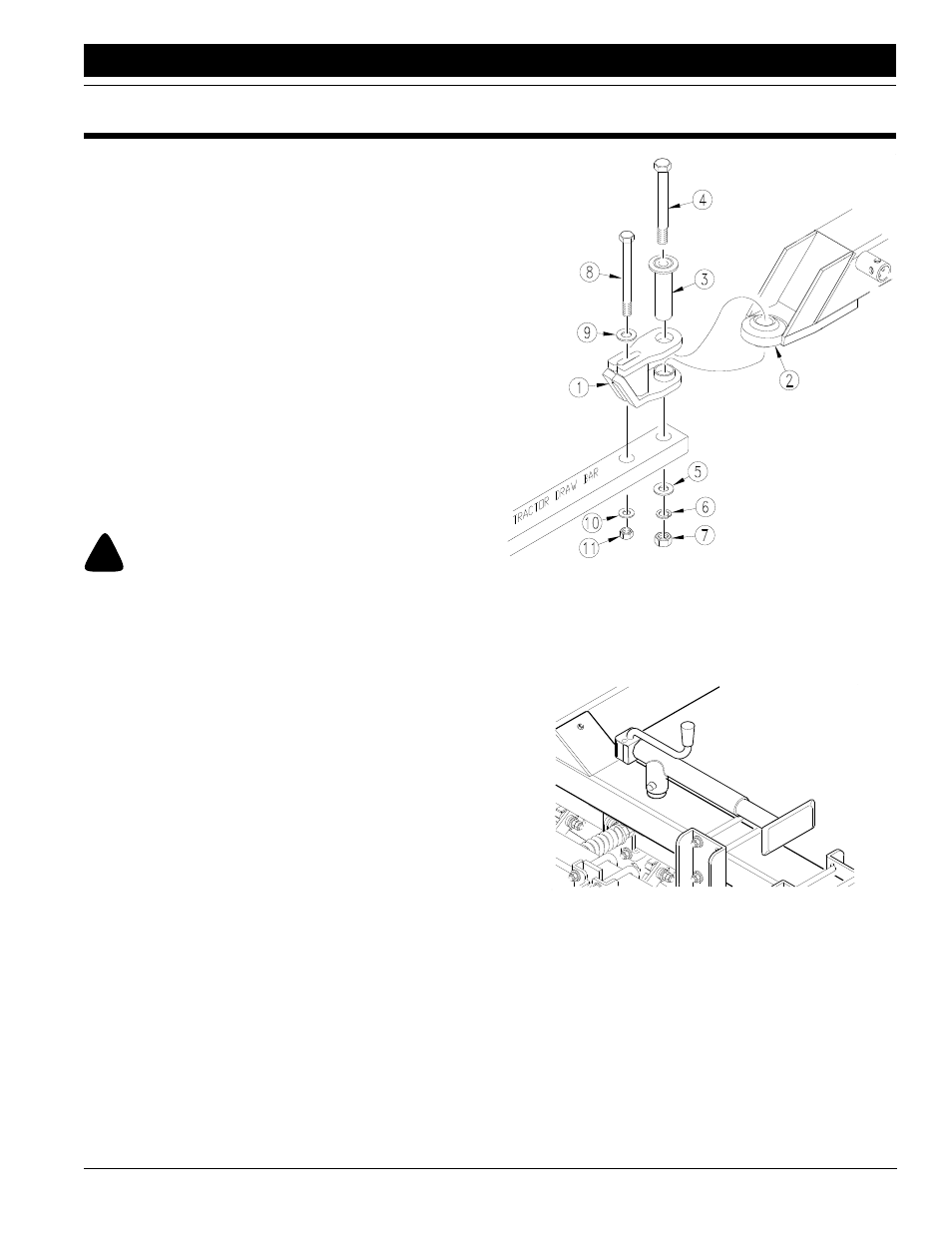
1.
Place hitch weldment (1) over ball swivel (2) on hitch
tongue. Hold hitch weldment in place by inserting
spacer tube (3) through hitch clevis and ball swivel.
2.
Back tractor up to hitch and bolt hitch weldment to
tractor drawbar using 1-by-10-inch bolt (4), large flat
washer (5), lock washer (6), and nut (7).
3.
Use 3/4-by-9-inch bolt (8) to bolt hitch weldment
through its slotted hole and onto secondary hole of
tractor drawbar. Install a 3/4-inch flat washer (9) next
to top slotted hole and fasten with a lock washer (10)
and nut (11). Tighten both bolts.
Figure 1-1
Drawbar Assembly Illustration
4.
Securely attach safety chain to tractor-drawbar frame.
5.
Remove jack from stob on side of hitch tongue and
place in transport position on frame brace. See Figure
1-2.
Figure 1-2
Jack in Transport
17215
12083