Marker adjustments, Marker disk angle, Marker speed – Great Plains 3PNG15 Operator Manual User Manual
Page 27: Folding speed with needle valves, Marker disk angle marker speed, Warning, Caution
Great Plains Manufacturing, Inc.
Adjustments
23
10/06/2008
202-553M
Marker Adjustments
See other sections for these marker items:
Marker Setup:
“Marker Extension Setup” on page 45
Marker Maintenance:
“Charge Hydraulic System” on page 45
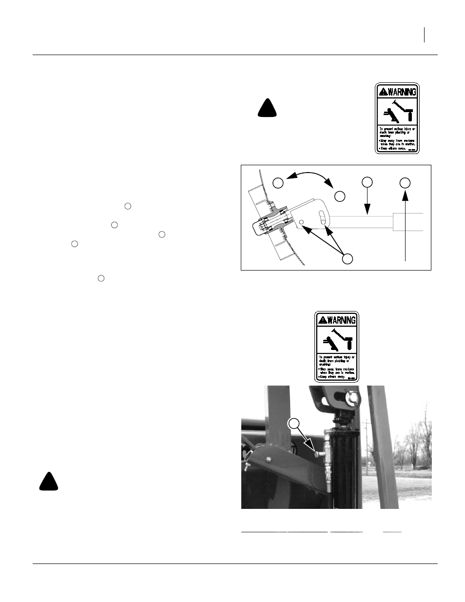
Marker Disk Angle
Refer to Figure 12
To change angle of cut, and the width of the mark:
1.
Loosen
1
⁄
2
-inch bolts
holding the disk assembly.
For a wider mark
, increase the angle of the
marker with respect to the tube
. For a narrower
mark
, reduce the angle.
To change direction of cut (throw dirt out vs. in), invert
disk blade on hub, or invert disk assembly on tube.
2.
Tighten bolts
.
Marker Speed
The folding speed of independent markers (on separate
hydraulic circuits) is controlled by needle valves at the
cylinders.
The folding speed of sequenced dual markers is con-
trolled by an adjustment at the sequence valve.
Excessive folding speed can damage markers and void
the warranty.
Folding Speed with Needle Valves
This applies only to markers plumbed separately (left
and right are each on their own tractor hydraulic circuit).
Refer to Figure 13
A needle valve controls the folding speed. The needle
valve is near the rod end of the marker cylinder. With
tractor idling at a normal operating speed, adjust marker
folding to a safe speed.
!
WARNING
Do not adjust needle valve while marker is in motion.
!
CAUTION
Marker disks may be sharp.
Use caution when making
adjustments in this area.
Figure 12
Marker Disk Angle
11757
2
1
N
W
T
2
W
1
N
2
1
Figure 13
Needle valve Adjustment
17620