Calibration overview, Calibrate with drill raised, Calibrate for 1/10th acre or hectare – Great Plains 3PNG15 Operator Manual User Manual
Page 26: Calibration crank storage, Using calibration crank, Calibration rotations, Calibrate with drill raised calibrate for, Calibration crank storage using calibration crank
22
3PNG12 and 3PNG15
Great Plains Manufacturing, Inc.
202-553M
10/06/2008
Calibration Overview
Detailed calibration steps vary with each box. Details are
found in the Seed Rate Manual.
Some general information applies to all boxes.
Calibrate with Drill Raised
Perform the calibration with the drill hitched and raised.
Calibrate for
1
/
10
th Acre or Hectare
The number of revolutions per area depends on whether
rotating the gauge wheel, or the crank, and if the crank,
what current Drive Type. See table at bottom of page.
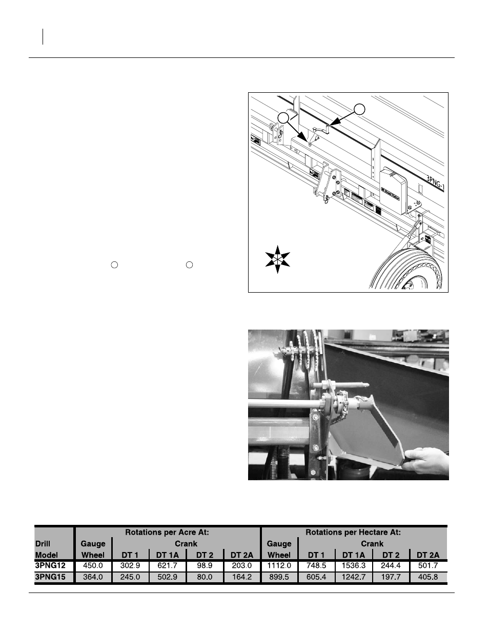
Calibration Crank Storage
2007 and later 3PNG drills include a calibration crank.
Earlier models rely on gauge wheel rotation.
Refer to Figure 10
The calibration crank
is stored at a stob
on the top
of the front frame. It is secured by a pin.
Using Calibration Crank
Remove the cotter pin from the drive cover at the left end
of the drill.
Remove the crank from the storage stob, and use its pin
to secure it to the exposed shaft end at the forward left
end of the drill.
Use the handle to rotate the shaft counter-clockwise.
A wide range of cranking speeds produce accurate cali-
brations. For reference, at 6 mph (10 kph) field speed,
tire rpm is about 60 (about 1 revolution per second).
Calibration Rotations
Figure 10
Calibration Crank Handle Stored
28480
2
U
D
F
B
L
R
1
Figure 11
Calibration Crank in Use
23467