Planting depth adjustments, Coulter hydraulic depth control, Down pressure requirements – Great Plains EWNT7 1237Q-1522Q Operator Manual User Manual
Page 24
EWNT7 and EWNT10 End Wheel No Till Drill 150-082M
4/17/2001
22
Great Plains Mfg., Inc.
Section 4 Adjustments
Planting Depth Adjustments
A no-till coulter is mounted independently and directly
ahead of each opener on the drill. Each coulter cuts
through heavy trash and/or cuts a groove in the firm soil
often encountered in no-till seeding conditions. The
coulters are mounted directly to the drill box frame. Con-
sequently, the cutting depth of all coulters on the drill
change as the drill is raised and lowered. The cutting
depth of the coulters is controlled by an adjustable hy-
draulic depth stop on the master cylinder. Refer to "Hy-
draulic Depth Control" for information on how to make
this depth adjustment.) Those coulters which run direct-
ly in drill and tractor tire tracks may be individually low-
ered if desired. See "Individual Coulter Adjustment".
Coulter Hydraulic Depth Control
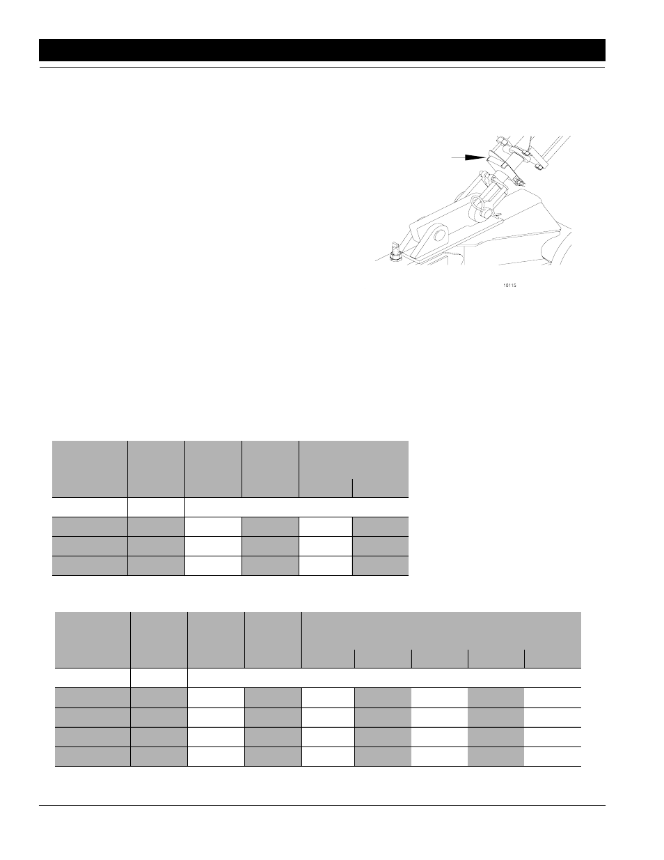
Refer to Figure 4-8:
The master lift cylinder on your drill is equipped with a
hydraulic depth control stop, Figure 4-8. This allows for
a variable adjustment from zero to maximum stroke
which controls the depth of your coulters. In order to ad-
just the stroke of the cylinder, retract the cylinder until the
coulters are penetrating at the desired depth required.
Next, loosen the bolt on the depth control actuator plate
and slide it up the cylinder until it stops against the
plunger of the control valve on the head of the cylinder.
You will now need to extend your cylinder slightly and
move the depth control actuator plate up to compensate
for the control valve plunger length.
Down Pressure Requirements
If more weight is required for your soil conditions, it
should be added to the weight bracket of the drill (option-
al equipment). Be sure the weights are equal at each
end. Refer to chart below for additional weights.
10115
Master Cylinder With Depth Control Stop
Figure 4-8
7’ Drill
Row
Spacing
Drill
Weight
Empty
Drill
Only
Drill With
*Weight
Bracket
Great Plains Weight
Bracket & Weight
Required
200#
600#
Pounds Per Coulter
7"
3800#
345#
375#
393#
421#
7 1/2" & 8"
3650#
365#
398#
418#
N/A
10"
3350#
418#
N/A
N/A
N/A
10’ Drill
Row
Spacing
Drill
Weight
Empty
Drill
Only
Drill With
*Weight
Bracket
Great Plains Weight Bracket & Weight Required
200#
600#
1000#
1200#
1400#
Pounds Per Coulter
7"
4500#
281#
302#
314#
340#
365#
377#
390#
7 1/2"
4350#
290#
312#
326#
352#
379#
392#
N/A
8"
4200#
300#
324#
338#
367#
395#
N/A
N/A
10"
3750#
340#
371#
390#
N/A
N/A
N/A
N/A
*7’ Weight Bracket Part No. 150-010A
**10’ Weight Bracket Part No. 150-011A