Clutch shaft & miter gear alignment, Seed rate adjustments – Great Plains EWNT7 1237Q-1522Q Operator Manual User Manual
Page 14
EWNT7 and EWNT10 End Wheel No Till Drill 150-082M
4/17/2001
12
Great Plains Mfg., Inc.
Section 4 Adjustments
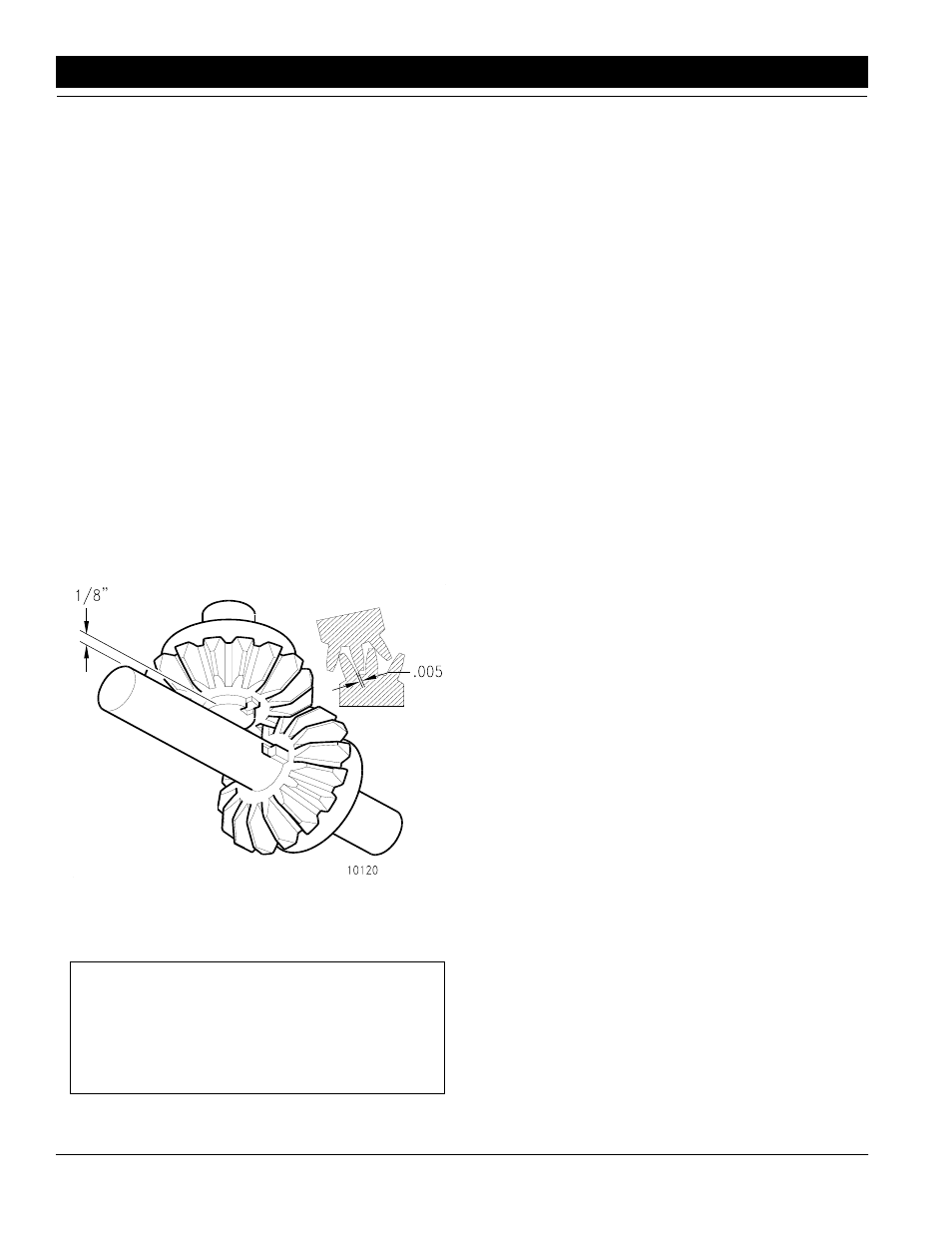
Clutch Shaft & Miter Gear Alignment
Refer to Figure 4-3:
The speed change box is designed to give you a variety
of speeds for different types of seeds and rates. It is a
linear shift pattern design with constant mesh gearing
and totally sealed to keep the dirt out. There should be
no lubrication required unless service is needed. The in-
put shaft is located on the bottom of the box and is driven
with mitered gears. It is recommended that lubrication
not be applied to the gears. If the gears are lubricated
the lubrication will attract dirt and increased wear will re-
sult. It is very important that the mitered gears back lash
is set correctly. Using a (.005) wire type feeler gauge or
a piece of wire measuring (.005) in diameter, insert it be-
tween the teeth of the two gears where they mesh, Fig-
ure 4-3. The adjustment is done by loosening the set
screws in the bearing on the jack shaft nearest the gear.
Loosen the bearing bracket mounting bolts under the
gearbox. Then slide bearing bracket, bearing and gear
over to gear on the gear box input shaft with wire gauge
inserted between the teeth and tighten the bearing set
screws, then tighten the bearing bracket mounting bolts.
After adjustments are made, rotate the jackshaft to see
that no binding occurs within the gears.
Seed Rate Adjustments
10120
Speed Change Miter Gears
Figure 4-3
NOTE: Seeding rates will vary greatly with variations
in sizes of the seeds. Although the seeding rates list-
ed in this manual are based on an average seed
size, we recommend that you test and adjust your
drill using the procedures listed below to help insure
an accurate seeding rate.
Refer to Figure 4-4:
1.
To adjust your seeding rate, first you must decide
which drive type you need (see "Seed Rate Charts"
on the following pages). In order to change drive
types, move the lever on the speed change box to
desired setting, Figure 4-4.
2.
There are many factors which will affect seeding
rates: seed treatment, weight of seed, size of seed,
surface condition of seed, and tire configuration,
pressure and slippage. Minor adjustments will prob-
ably be needed to compensate for the above factors.
3.
The pounds-per-acre in the seed charts are based
on drills having 9.00 x 24 rib implement tires with
proper inflation as listed on page 6.
4.
The large differences in seed size and treatment can
cause a wide variation in actual seeding rates. The
seed rate charts on the following pages are based
on average size seed. This may differ from the seed
you are using. Use the seed rate charts as a guide.
Set the pounds-per-acre desired at the indicator
number for your row spacing and complete the fol-
lowing procedure to calibrate the drill for your specif-
ic seed.
a.
Lower the drill hydraulically to planting position
in order to activate the clutch.
b.
Raise the drive (left) end tire off the ground us-
ing a jack.
c.
Rotate the tire to see that the drive system is
working properly and that the feed cups are free
from foreign matter.
d.
Place several pounds of seed over three of the
feeder cups at the outboard end of the seed box.
Make sure all feed cup handles are set in the
same position on all the feeder cups.
e.
Set the feed cup adjustment lever to the desired
setting.
f.
Pull the seed tubes out of these openers.
g.
Place a container under the three seed tubes to
gather the seed as it is metered.
h.
Rotate the drive gauge wheel until one acre has
been tallied on the acremeter. This will be ap-
proximately 422 rotations on a 10’ drill and 592
rotations on a 7’ drill. Be sure to check the three
feeder cups to make sure each cup has plenty of
seed coming into it.
i.
Weigh the seed which has been metered. Di-
vide by three. This will give you the ounces/
pounds metered by each feeder cup. Multiply by
the number of openers on your drill to arrive at
the total pounds-per-acre you would meter at
that setting. If this figure is different than de-
sired, set your feed cup adjustment lever ac-
cordingly.