Adjustments, Side gauge wheels for 20 series openers – Great Plains 2420F Operator Manual User Manual
Page 27
8/14/2006
25
Adjustments
Side Gauge Wheels for 20 Series
Openers
Refer to Figure 18
The side gauge wheels have two, interrelated adjustments:
• angle of side gauge wheel, and
• distance between side gauge wheel and row unit disk.
Refer to Figure 19
Adjust side-gauge-wheel angle so wheels contact the row
unit disks at bottom of wheel at 2” planting depth.
At the same time, keep side gauge wheels close to the
opener disks so openers do not plug with soil or trash but
far enough out so the disks and wheels turn freely.
• If contact point is between 4 to 8 o’clock but dis-
tance to tire is not correct, then add or remove shims
as needed. DO NOT ADJUST BEARING AS THAT
WILL ADJUST WHEEL-TO-DISK CONTACT AREA
ONLY.
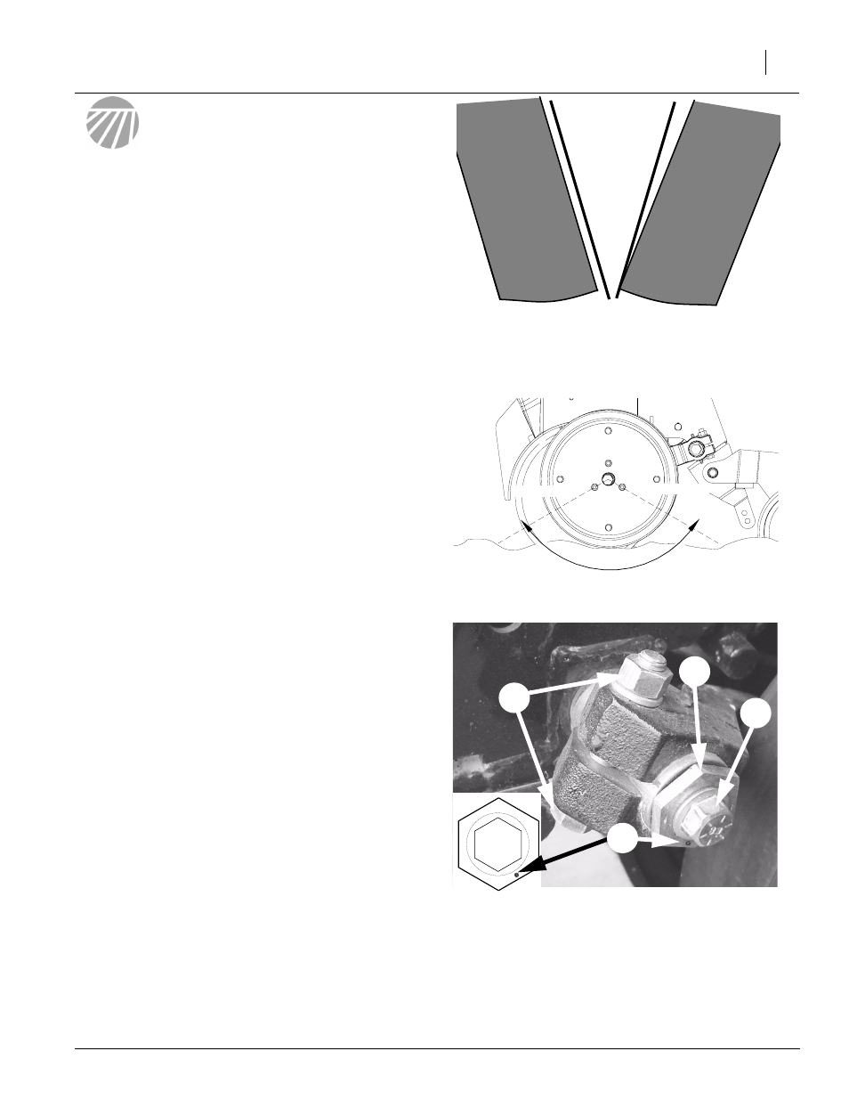
Refer to Figure 20
To adjust Wheel-to-Disk contact area of side gauge
wheels:
1.
Raise drill slightly to remove weight from side gauge
wheels.
2.
Loosen hex-head bolt (1). Move wheel and arm out on
o-ring bushing.
3.
Loosen pivot bolt (2). Turn hex adjuster (3) so indicator
notch (4) is at 5 o’clock to 7 o’clock. Use this as the
starting point for adjustment.
4.
Move wheel arm in so side gauge wheel contacts row
unit disk. Tighten hex-head bolt (1) to clamp arm
around bushing and shank.
5.
Check wheel-to-disk contact at 2” planting depth. Lift
wheel and arm. When let go, wheel should fall freely.
• If wheel does not contact disk at bottom to area
where blade leaves contact with soil, move hex ad-
juster until wheel is angled for proper contact with disk.
• If wheel does not fall freely, loosen hex-head bolt (1)
and slide wheel arm out just until wheel and arm move
freely. Retighten hex-head bolt (1) according to grade:
• 7/16” Gr 8 bolt on 20 series, 70 ft-lbs.
• 5/8” Gr 8 bolt on 20 series, 150 ft-lbs.
NOTE: Use “Torque Values Chart”, page 56 for reference.
Figure 19
Wheel-to-Disk Contact Area
24006
8 o’clock
4 o’clock
Figure 20
Side Gauge Wheel Adjustment
Starting Point
22525
2
1
3
4
6.
Keep turning hex adjuster and moving wheel arm
until the wheel is adjusted properly. When satis-
fied, tighten pivot bolt (2) to 110 foot-pounds.
Adjustments
Side Gauge
Wheel
Side Gauge
Wheel
Opener
Disks
Incorrect
Correct
Figure 18
Side Gauge Wheels
Note: Wheel touches at bottom and gaps open 3/8”
to 5/8” at top.