General operation and in-field adjustments, Prior to operating the turbo max, Hitch turnbuckle – Great Plains 4000TM Operator Manual User Manual
Page 34: Prior to operating the turbo max hitch turnbuckle, General operation and in-field adjust- ments
30
1200-4000TM
Great Plains Manufacturing, Inc.
586-288M
10/30/2012
General Operation and In-Field Adjust-
ments
Prior to Operating the Turbo Max
11. Raise the machine fully so the lift cylinders
no longer rest
on the transport lock channels
Remove transport lock channels and store on the bars
above. Remove the wing transport pins
and store in the spools
on the wing rest bar. Open the
wing fold valve
located under the depth stop adjustment
(Models 1800-3000) or on the bypass/down pressure valve
(Models 3500-4000). You are now ready to unfold unit.
12. Unfold unit being sure that the fold cylinders are fully
extended. You may increase flow rates during the folding
and unfolding procedure but be sure to slow the flow rates
back down once the unit is unfolded.
13. When operating the Turbo Max with the blades running at
an angle, it is generally unnecessary to operate with
hydraulic down pressure to the wings. Only in very hard
ground will down pressure be needed. If down pressure is
needed, see “Hydraulic Down Pressure 1800-3000” on
page 23, “Hydraulic Down Pressure 3500” on page 24 or
“Hydraulic Down Pressure 4000” on page 25 for initial
setup. If no down pressure is needed, set the fold hydraulic
system to the "FLOAT" position at this time.
14. When operating the blades in the straight position, down
pressure is necessary, usually between 200 and 400 psi.
Note: Never leave tractor valve centered when unfolded with
machine in motion. Machine damage may occur when
wings flex. The hydraulic down pressure cylinders have
no wing flex capability and oil flow is required when the
wings flex up or down. You must have the tractor fold hy-
draulic lever in continuous downward flow or “FLOAT” po-
sition before the wings can flex over terrain in the raised
or lower lift position.
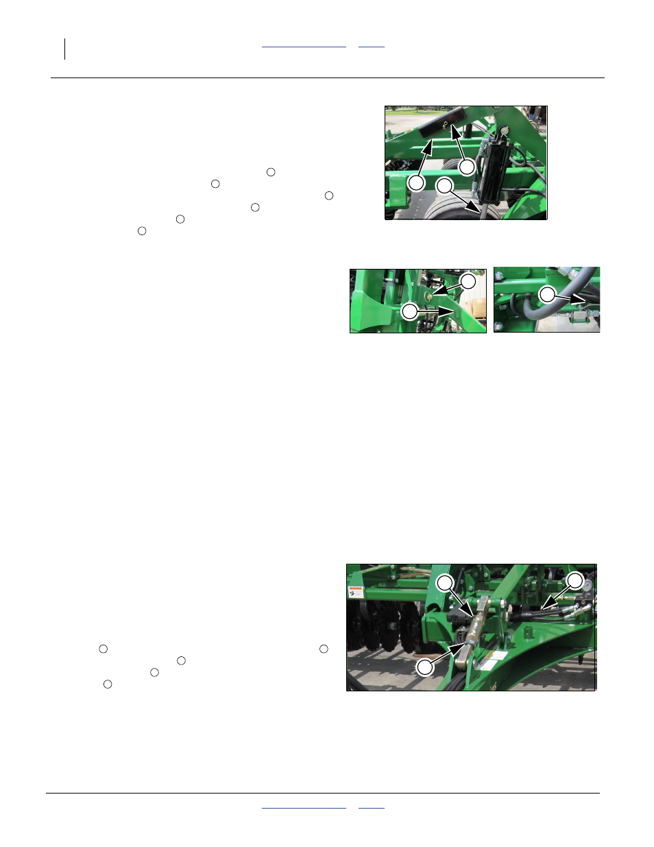
Hitch Turnbuckle
Note: If possible have someone observe the machine during
the initial operation for levelness - both front to rear and
center to wings. Adjust each as needed.
Refer to Figure 30
15. For front to rear, either extend or shorten the front turn-
buckle
on the leveling system by loosening jam nut
with turnbuckle wrench
(stored on rear pegs of hitch).
Adjust turnbuckle
until level front to back. Re-tighten
jam nut
after machine is level. Never run the machine
lower (deeper) in the rear than in the front.
Figure 28
Transport Locks
42066
1
2
3
1
2
3
4
5
6
Figure 29
Wing Fold
4224
4225
5
4
6
Figure 30
Hitch Turnbuckle Adjustment
42260
1
2
3
1
2
3
1
1