Step 12: 5 revolution test, 4step 13: summary screen, Step 11: clutch folding module operation – Great Plains YP4025A-3115 31-Row 15-Inch Quick Start User Manual
Page 4: Step 9: accessory sensor setup, Step 10: clutch folding module (cfm) setup
Quick Setup Guide for IntelliAg Model YP40 15” Air Pro
11001-1539-200909
©2009 DICKEY-john Corporation
Specifi cations subject to change without notice.
STEP 12: 5 Revolution Test
Press the Control Setup button
.
Press the Channel Setup button
.
Press the Next Page button
.
Ensure implement is raised before starting 5 Rev Test.
With brakes locked and transmission in PARK position, start tractor engine.
Engage hydraulics and run engine at normal speed until hydraulic fl uid is at operating
temperature.
Press the 5 Rev button
.
Test Ground Speed and Row data must be entered to perform test.
Press and hold remote test button to initiate 5 Rev Test.
1.
2.
3.
4.
5.
6.
7.
8.
9.
4
STEP 13: Summary Screen
The Summary screen provides an overview of setup constants for active control channels.
At the Main Work screen, press the Next Page button
.
Press the Summary button
To view specifi c control channel confi gurations, press the respective control channel
box 1-4.
Press inside a yellow highlighted box to open a specifi c screen for editing.
Press the Work Screen button
to return to the Main Work screen.
1.
2.
3.
4.
5.
Summary
Screen
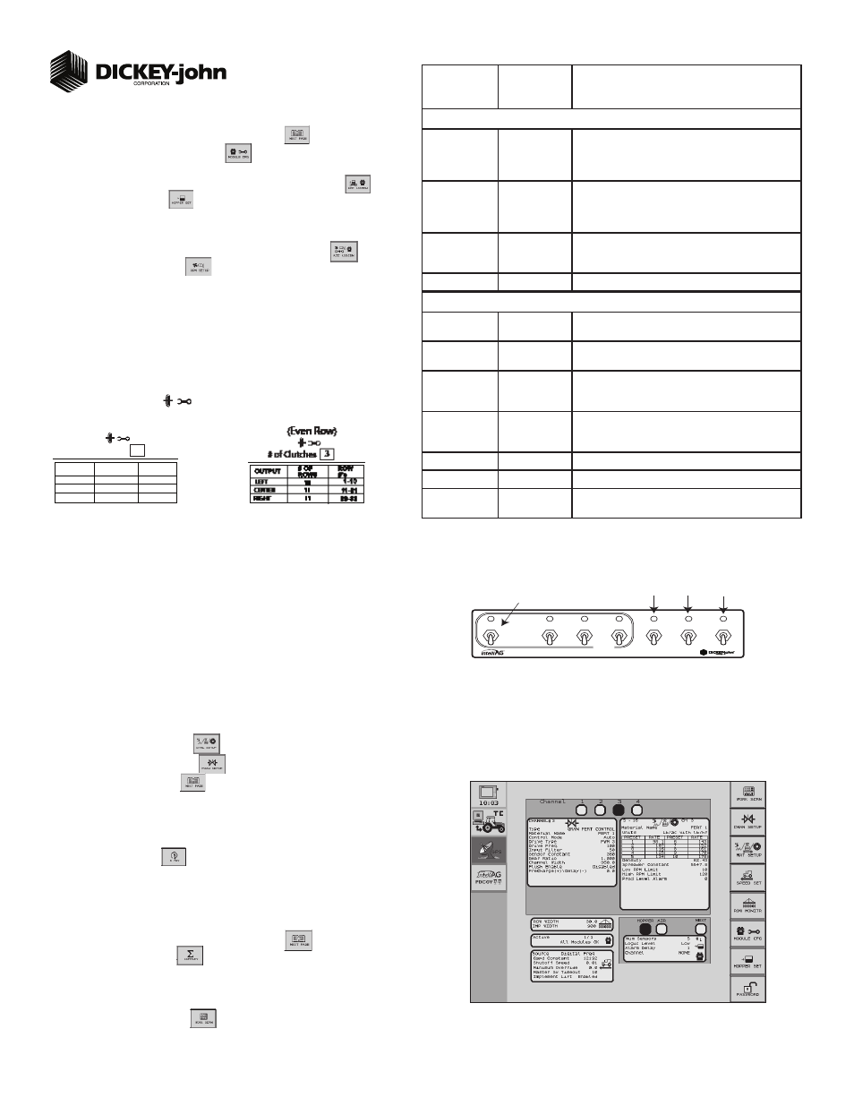
STEP 11: Clutch Folding Module Operation
The planter section controls turn the left, center, and right clutch controls on and off.
The master switch must be in the ON position to activate any planter section. When a
clutch control is ON, a green light will illuminate.
Marker/Fold Switch should be in the UP (Marker) position during planting. In the
DOWN (Fold) position, the switch controls the fold of the main frame.
The fertilizer pump switch is turned ON when in the UP position. Press the switch in the
DOWN position to turn OFF.
Lift/Hitch switch should be in the UP (Lift) position during normal operation. In the hitch
position, the switch should be in the DOWN (Hitch) position to unlock and extend the
telescoping tongue in preparation of folding the implement for transport.
Lift/Hitch switch MUST be in the hitch position and hydraulic circuit in FLOAT when
transporting planter equipped with hydraulic-operated tongue hitch. NOTE: Lift/Hitch
switch has no function if planter has standard 3-point hitch operated tongue hitch.
1.
2.
3.
4.
5.
6.
MASTER
Left Center Right Marker Fert. Pump Lift
MASTER
MASTER
CLUTCH
Fold Hitch
Master
CFM Switch
Marker
or
Fold
Fertilizer
Pump
On/Off
Lift
or
Hitch
TABLE F:
Accessory
Setup
Default Value
or Value to
Enter
Instructions/Defi nitions
Hopper Setup
# of Hoppers
1 (base unit)
1 more (optional)
# of hopper sensors connected to each module (4 sensors
maximum). # of hopper data items for each listed module
and the Hopp #’s value will automatically populate if Auto
Confi g is used to confi gure installed sensors.
Logic Level
Active Lo
Sets the active state to low signifying that an alarm is gener-
ated if the sensor’s output is in a low state. Use this setting
if the connected sensor outputs a low condition when empty
similar to the DICKEY-john hopper sensor.
Alarm Delay
5 sec
Controls the delay time between the detection of a high/low
hopper alarm condition and the generation of the resulting
alarm. The value is entered in seconds.
Channel
Assigns hopper sensor to channel.
RPM Setup
High Alarm
(fan speed)
3000 rpm
Sets the RPM value at which a high RPM warning error is
generated.
Low Alarm
(fan speed)
1800 rpm
Sets the RPM value at which a low RPM warning error is
generated.
High Alarm Delay
10 sec
Establishes the delay between the detection of a high RPM
alarm condition and the resulting alarm display. The value is
entered in seconds.
Low Alarm Delay
10 sec
Establishes the delay between the detection of a low RPM
alarm condition and the resulting alarm display. The value is
entered in seconds.
RPM Constant
3 pulses/rev
Number of pulses per sensor revolution.
RPM Filter
0
Filters the signal out of the RPM sensor.
Disable Control
on Low Alarm
Disabled
Allows for disabling of all control channels if the RPM value
of the selected sensor falls below the low alarm level setting.
STEP 9: Accessory Sensor Setup
Hopper Assignment
At the Main Work screen, press the Next Page button
.
Press the Module Confi guration button
to display the Module Confi guration
screen.
At the Module Confi guration screen, press the Hopper Assign button
.
Press Hopper Set button
.
Enter desired values using Table F as reference.
RPM Assignment
At the Module Confi guration screen, press the Acc Assign button
.
Press the RPM Setup button
.
Enter # of RPMs, if required. NOTE: There must be at least 1 RPM sensor confi gured
before the RPM Setup button appears on the screen.
Enter desired values using Table F as reference.
1.
2.
3.
4.
5.
1.
2.
3.
6.
STEP 10: Clutch Folding Module (CFM) Setup
The CFM is installed in the cab to control row clutches, marker, fold, fertilizer on/off, lift and
hitch.
At the Main Work screen, press the Clutch CFG button to access the Clutch Confi gura-
tion screen and verify that the correct # of clutches are confi gured for the system.
The Clutch CFG button
only appears as a top level button when a planter
output module and clutch folding module are installed.
1.
2.
O U T P U T
1 - 1 0
# O F
R O W S
R O W
# ’s
11 - 2 1
2 2 - 3 1
LEFT
CENTER
RIGHT
10
11
10
# of Clutches 3