Great Plains YP4025A-3115 31-Row 15-Inch Quick Start User Manual
Page 3
Quick Setup Guide for IntelliAg Model YP40 15” Air Pro
11001-1539-200909
©2009 DICKEY-john Corporation
Specifi cations subject to change without notice.
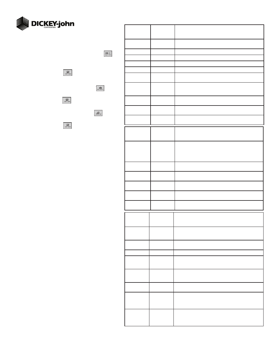
TABLE C2:
Planter Control
Setup
Default Value
or Value to
Enter
Split Air Regulation
Instructions/Defi nitions
Type
Split Air
Regulation
Confi gure Control Channel 2 as Split Air Regulation.
Material Name
Air
Create Material Name as “Air”.
Control Mode
Auto
Control channel feedback based on air pressure sensor.
Drive Type
Air Reg 2
Automatically selects Air Reg 2 as drive type.
Input Filter
79%
Amount of fi ltering applied to the control channel feedback frequency.
Pressure Drop
0
Difference in pressure sensor mounting location to the seed disk in
inches of H20.
Pressure Slope
447.2269
The change in pressure sensor voltage to a frequency readable by the
IntelliAg system and measured in inches of H20. Should only be adjusted
by qualifi ed personnel.
Pressure Offset
800
Takes a zero point reading that provides a frequency when the fan is off.
Press the Zero Pressure button to calculate frequency.
Planter Selection
YP40
Select Planter Selection of YP40 to automatically adjust to the appropri-
ate calibration settings.
Sensitivity Adjust
0
Increases or decreases the calibration parameters in the ranges of -10 to
+10. Increasing resonse time makes the system respond quicker.
STEP 6B: Planter Control Channel Setup
(Split Air Regulation)
NOTE: Split Air Regulation must be confi gured as Control Channel 2 only.
At the Channel Setup screen, press the Next Channel button
.
At Channel 2 screen, select Split Air Regulation as the Type.
Enter desired values from Table C2.
Press the Work Screen button
to return to the Main Work screen.
1.
2.
3.
4.
TABLE E:
Speed
Set
Default Value
or Value to
Enter
Instructions/Defi nitions
Source
Digital Frequency
Select CAN Ground if radar is connected to ISO tractor cab harness.
Select Digital Frequency if radar or hall-effect is connected to WSMT
actuator harness.
Gspd Constant
12192
Input based on pulse count produced by the ground speed sensor over
400’ distance. See Operator’s manual for calibration instructions.
Shutoff Speed
0.5 mph
Set desired minimum ground speed allowed before the system shuts off.
Minimum
Override
2.0 mph
Set to operate when actual ground speed falls below the designated
value. Control will operate at this speed until actual ground speed rises
above minimum override speed or actual speed drops below shutoff.
Master Sw
Timeout
10
Set to desired number of seconds system shuts off if the master switch is
turned on and there is no ground speed. Toggle master switch to restart
the system and turn off alarm.
Gspd Fail Alarm
Delay
5
Set to desired number of seconds alarm sounds after the ground speed is
zero and seed fl ow continues. (Monitor only)
Precharge
Ground Speed
0
Set to the desired speed the system will use when a precharge time has
been enabled for a control channel. Refer to Table C1: Planter Control
Setup for Precharge Time. This setting will only display when a Precharge
Time has been entered.
Implement Lift
Enabled
Implement lift switch, when enabled, displays an implement lift indicator
on the Main Work screen indicating implement lift position as up or down.
Control channels can be turned on and off without using the master
switch.
3
STEP 8: Speed Set Calibration Setup
At the Main Work screen, press the Speed Set button
.
Enter desired values using Table E as reference.
Press the Work Screen button
when ground speed calibration
confi gurations are complete to return to the Main Work screen.
1.
2.
3.
STEP 7: Row Monitor Setup
At the Main Work screen, press the Row Monitor button
.
Enter desired values using Table D as reference.
Press the Work Screen button
to return to the Main Work screen.
1.
2.
3.
TABLE D:
Row Monitor
Setup
Default Value
or Value to
Enter
Instructions/Defi nitions
Material Name
See Instructions
Material Name only appears on the Row Monitor Setup screen when
all control channels are disabled and material is set for Monitor Only.
This is only used for ground drive/nonhydraulic applications to monitor
population with high and low alarms. A material must be confi gured and
selected to activate alarms.
High Alarm Delay
5
Desired number of seconds that high population can be above high
alarm point before alarm will sound.
Low Alarm Delay
5
Desired number of seconds that low population can be below low alarm
point before alarm will sound.
Population Adjust
100
Enter a % to allow for seed sensor population inaccuracies to achieve
the desired population display. 100% represents true calculation.
Population Filter
50
Set fi lter value to stabilize the monitored population display. Number can
be set to 0% for no fi ltering and 99% for high level fi ltering.
Row Fail Rate
2/1 (2 seeds
every 1 second)
Set to desired number of seeds per second to trigger seed sensor failure
alarm.