Great Plains 4000-3S Assembly Instructions User Manual
Page 4
195-252M
2/17/2005
Great Plains Mfg., Inc.
Point-Row Option
4
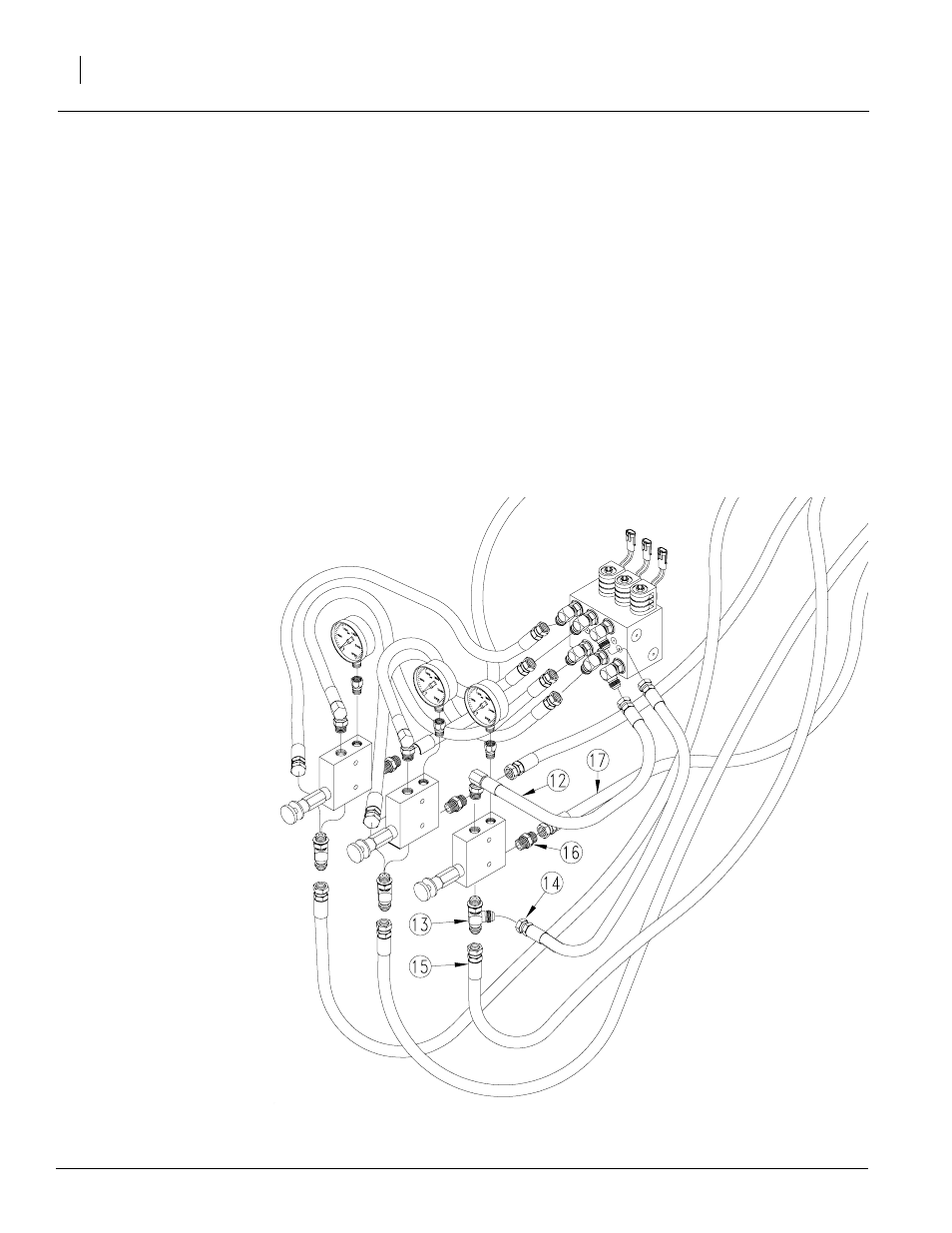
Refer to Figure 6
6.
Assemble new 21" hose (12) to top-front port
on new pressure control valve. Using tee fit-
ting (13), assemble new 18" hose (14) and
one new 72" hose (15) to bottom port. Using
adaptor fitting (16), assemble remaining 72"
hose (17) to rear port.
7.
Route 72" hoses (15 and 17) from new pres-
sure control valves back along top of drill
frame.
8.
Connect short hoses to new block. Connect
21" hoses to lower-front ports in block. Con-
nect 18" hoses to top-front ports in block.
Connect hoses to block in same order as
valves. (For example, connect hoses from
center valve to center ports in block.)
Figure 6
17087
See also other documents in the category Great Plains Gardening equipment:
- 1200 Parts Manual (210 pages)
- 706NT Material Rate (46 pages)
- 706NT Material Rate (50 pages)
- 2N-2410 Operator Manual (56 pages)
- 2N-2410 Operator Manual (48 pages)
- 12 Series Drills Assembly Instructions (6 pages)
- X-PresS 2006 Assembly Instructions (50 pages)
- TM500 Operator Manual (62 pages)
- 2010HDP Operator Manual (166 pages)
- YP1630F Material Rate (42 pages)
- YP2425 Operator Manual (162 pages)
- 3S-5000 Operator Manual (94 pages)
- 3PYP Operator Manual (188 pages)
- 3N-3010P Assembly Instructions (2 pages)
- 3N-3010 Assembly Instructions (9 pages)
- 3N-3010P Assembly Instructions (9 pages)
- PFH-15 Predelivery Manual (23 pages)
- PFH-15 Operator Manual (46 pages)
- PFH-15 Operator Manual (26 pages)
- P15126 Serial No 12724 (34 pages)
- DVN 8321 Operator Manual (38 pages)
- 3P500 Assembly Instructions (22 pages)
- 605NT Assembly Instructions (4 pages)
- 3P600 Assembly Instructions (12 pages)
- 605NT Assembly Instructions (8 pages)
- CPH-12 Assembly Instructions (3 pages)
- YP1625A-2420 24 Row 20-Inch Quick Start (6 pages)
- 8323 FCF Predelivery Manual (124 pages)
- P13937 (20 pages)
- 3323 DH Parts Manual (114 pages)
- YP3025-1820 25 Series 18 Row 20 Inch Quick Start (5 pages)
- CF500 Operator Manual (38 pages)
- PFH-15 Assembly Instructions (30 pages)
- 3500TM Parts Manual (106 pages)
- 1800TM Parts Manual (158 pages)
- YP2425A-2470 24 Row 70 cm Quick Start (5 pages)
- Simba Culti Press Operator Manual (38 pages)
- RU1999 Parts Manual (58 pages)
- 3N-30P Assembly Instructions (10 pages)
- 2510HDP Operator Manual (180 pages)
- YP1220 Parts Manual (136 pages)
- 3P500 Material Rate (68 pages)
- YP2425-3620 36 Row 20 Inch Quick Start (5 pages)
- 706NT Operator Manual (22 pages)
- 706NT Operator Manual (53 pages)