Trusses, Hitch & center lift assembly, Trusses hitch & center lift assembly – Great Plains TCN5313 Assembly Manual User Manual
Page 12
8
TCN5107-5313
Great Plains Manufacturing, Inc.
566-170Q-ENG
03/17/2014
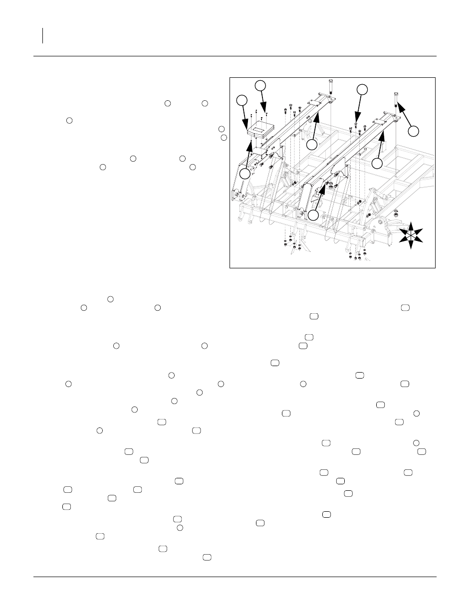
Trusses
Refer to Figure 7
23. Start by bolting the rear of the LH
and RH
trusses to center frame using 1 1/4 x 8 1/2 Gr. 8 hex
bolts
, 1 1/4 lock washers and 1 1/4 nuts. Attach
middle plates of trusses with 3/4 x 2 1/2 hex bolts
,
3/4 lock washers, 3/4 nuts, front plates with 3/4 x 2
3/4 lock washers, and 3/4 nuts.
24. Mount the manual pack
to RH truss
plate with 1/
4 x 1 hex bolts
, mini end press wheels
, 1/4 lock
washers and 1/4 nuts.
25. All bolts may be tightened to specs, See “Torque
Hitch & Center Lift Assembly
Refer to Figure 8
26. Attach hitch pole
to trusses using 1 1/4 x 8 Gr. 8
hex bolts
, 1 1/4 flat washers
(one on each side
of uni-ball) and top lock nuts. Washers are needed to
ensure a tight fit. Bolts need tightened securely, but
do not over-tighten as the hitch needs to pivot.
27. Mount square jack
to front mount on hitch
with
pin provided with jack. Use jack to help support front
of hitch for rest of hitch assembly.
28. Attach the four lift mechanism links
to the level bar
links
and torque tube with 1 x 6 Gr. 8 hex bolts
,
and 1 lock nuts. Attach rear of level bar link
to cen-
ter frame ears with 1 x 2 29/64 pins
, 1.5 x 1.0
x.075 machine washers
and 3/16 x 2 cotter pins.
29. Attach the rear of the level bars
to the top of the
level bar links
with 1 x 6 Gr. 8 hex bolts
and 1
lock nuts.
30. Attach level bar brace
between the level bars
using 5/8 x 1 1/2 hex bolts
, 5/8 lock washers and
5/8 nuts.
31. Now the back of the hitch turnbuckle
, turnbuckle
lock
and leveling arm
may be attached to the
front of level bars
with 1 1/4 x 9 special thread hex
bolt
and 1 1/4 lock nut.
32. The bottom of the hitch leveling arm
can be
attached to the back of the hitch pole
using 1 x 7
Gr. 8 hex bolt
and 1 lock nut.
33. The front of the hitch turnbuckle
may be attached
to the hitch pole ears with 1 x 3 5/8 clevis pin
, 1.5
x 1.0 x.075 machine washers and 3/16 x 2 cotter
pins. Attach the 3/8 x 4 pin wire snap lock
to the
turnbuckle lock
.
34. If machine is equipped with optional brakes, install
air line holder
, through first coil of spring in the
hose holder
. Secure by aligning holes in hose
holder and hole on air line holder, install 1/2 x 1 hex
bolt
,1/2 flat washer, 1/2 lock washer and 1/2 nut.
35. Attach counterbalance valve
to the plate on front
of hitch pole
with 5/16 x 3 1/2 hex bolts
and 5/
16 lock washers.
36. Align holes in safety chain support
, cat III hitch
tongue
with holes on left side of hitch pole
,
secure with 1 x 8 Gr. 8 special hex bolts
, 1 lock
washers and 1 nut.
37. Install safety chain
on bottom side of hitch
,
secure with 7/8 x 3 hex bolt
, 7/8 flat washer
, 7/
8 lock washer and 7/8 nut.
38. Attach hitch clevis
to cat III hitch tongue
with 3/
4 x 5 1/2 Gr. 8 hex bolt
and 3/4 lock nut.
Note: Do not use hitch clevis
if tractor has a hammer
strap. Use for transporting with truck.
39. Route safety chain
through safety chain support
.
40. All bolts may be tightened to specs, See “Torque
Figure 7
Truss
42008
4
3
7
6
2
U
D
F
B
L
R
1
5
8
1
2
3
4
5
6
2
7
8
1
2
3
4
1
5
6
7
6
8
9
10
6
11
12
13
14
15
16
10
17
16
1
18
14
19
20
15
21
22
23
24
1
25
26
27
1
28
29
1
30
31
32
27
33
32
29
26