Assembly, Torque tube, Center lift & gang mount – Great Plains TCN5313 Assembly Manual User Manual
Page 11: Torque tube center lift & gang mount
03/17/2014
566-170Q-ENG
Great Plains Manufacturing, Inc.
7
Assembly
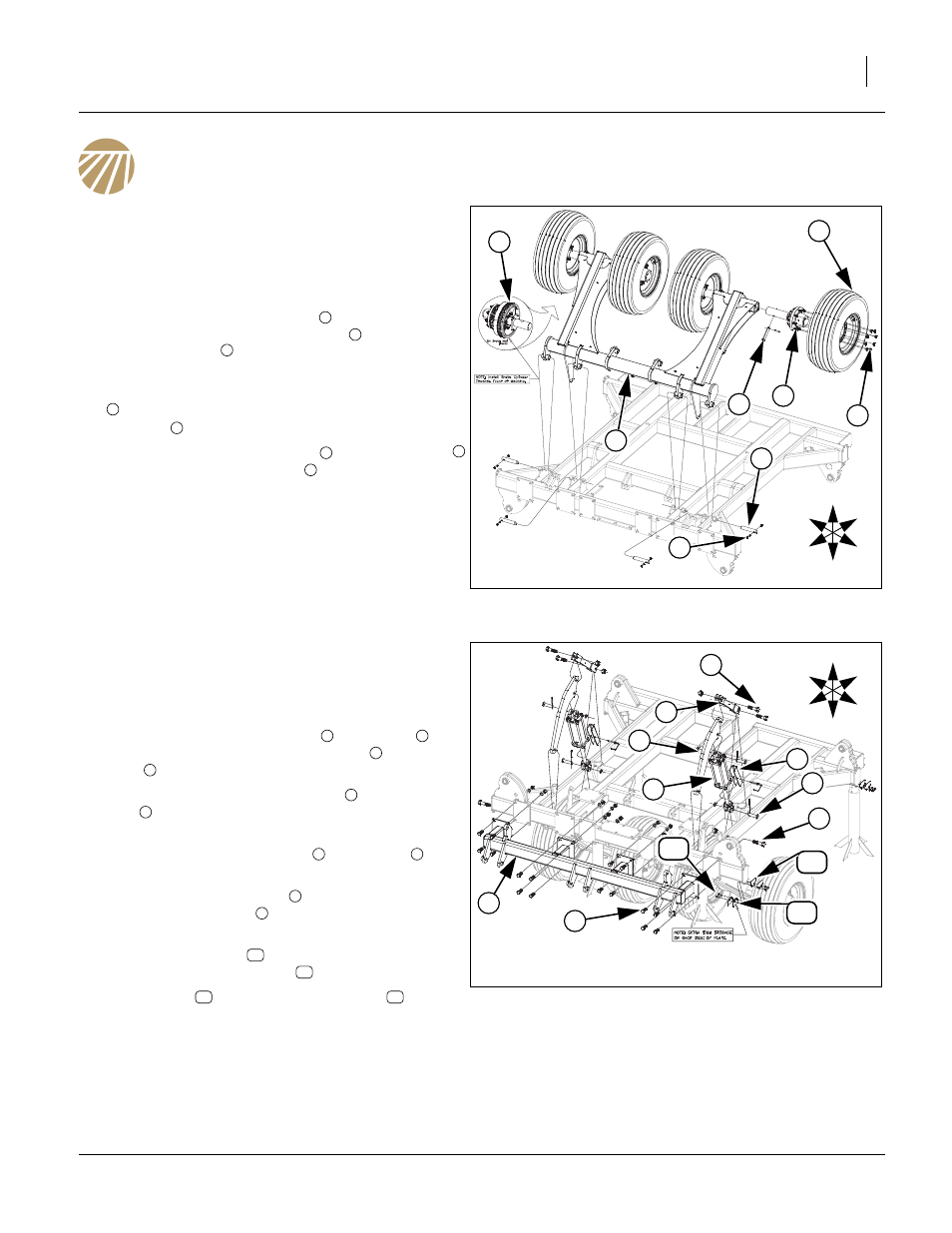
Torque Tube
Refer to Figure 5
11. Once the center Frame has been uncrated, carefully
turn the center frame upside down and set on blocks
to assemble torque tube.
12. Carefully raise the torque tube
with an overhead
hoist and secure with 1 1/4 x 7 pins
, 3/8 x 2 1/4 Gr.
8 special thread
and 3/8 top lock nut.
13. Install pre-assembled hub assembly or brake hub
(LH and RH, on outside spindle locations) assembly
(if machine is equipped with brakes) using the 1 x
4 5/8 pin
and secure with 3/8 x 2 roll pin.
14. Attach the tire/wheel assembly
to hub assembly
and secure with 5/8 lug nuts
.
15. All bolts may be tightened to specs, See “Torque
Center Lift & Gang Mount
Refer to Figure 6
16. Carefully raise center frame up from front bar and
turn over and set on stands.
17. Attach the cylinder mount bars
and lift link
to
center frame using 1 x 3 1/2 hex bolts
, 1 x 4 hex
bolts
and lock nuts.
18. Now install 4 x 10 x 1.38 cylinders
using 1 x 3 1/8
pins
, 1.5 x 1.0 x.075 machine washers and 3/16 x
2 cotter pins.
19. Install cylinder transport locks
to cylinders
using
the 5/16 wire retainer pin.
20. Attach center gang mount
to front of center frame
with 3/4 x 2 hex bolts
, 3/4 lock washers and 3/4
nuts.
Note: Store extra shims
on back side of end plate fac-
ing down with same bolts
that hold rest of shims.
21. Install shims
with 3/8 x 1 1/4 hex bolts
, 3/8 lock
washers and 3/8 nuts.
22. All bolts may be tightened to specs, See “Torque
Figure 5
Torque Tube
42006
2
6
3
4
1
U
D
F
B
L
R
4
5
7
1
2
3
4
5
6
4
7
Figure 6
Center Lift & Gang Mount
42007
8
2
3
9
1
U
D
F
B
L
R
6
7
5
4
11
10
10
1
2
3
4
5
6
7
5
8
9
10
11
10
11